GENERAL DESCRIPTION
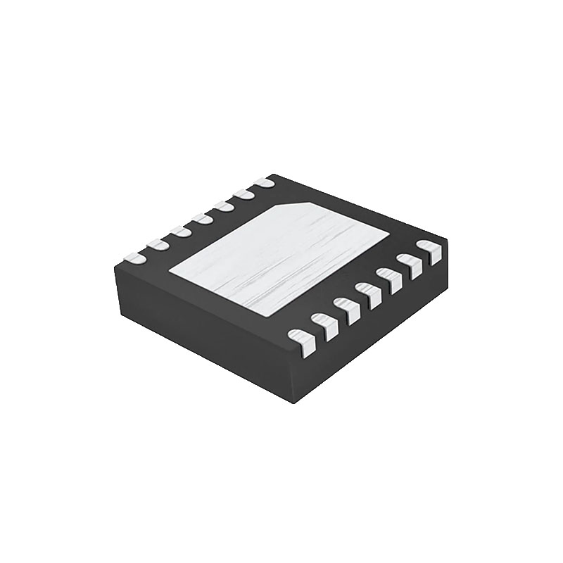
The ADF41513 is an ultralow noise frequency synthesizer that can be used to implement local oscillators (LOs) as high as 26.5 GHz in the upconversion and downconversion sections of wireless receivers and transmitters. The ADF41513 is designed on a high performance silicon germanium (SiGe), bipolar complementary metal-oxide semiconductor (BiCMOS) process, achieving a normalized phase noise floor of −235 dBc/Hz. The phase frequency detector (PFD) operates up to 250 MHz (integer N mode)/125 MHz (fractional-N mode) for improved phase noise and spur performance. The variable modulus, ∑-Δ modulator allows extremely fine resolution when using a 49-bit divide value. The ADF41513 can be used as an integer N phase-locked loop (PLL), or it can be used as a fractional-N PLL with either a fixed modulus for subhertz frequency resolution or variable modulus for subhertz exact frequency resolution. A complete PLL is implemented when the synthesizer is used with an external loop filter and voltage controlled oscillator (VCO). The 26.5 GHz bandwidth eliminates the need for a frequency doubler or divider stage, simplifying system architecture and reducing cost. The ADF41513 is packaged in a compact, 24-lead, 4 mm × 4 mm LFCSP.
FEATURES
1 GHz to 26.5 GHz bandwidth
Ultralow noise PLL
Integer N = −235 dBc/Hz, fractional-N = −231 dBc/Hz
High maximum PFD frequency
Integer N = 250 MHz, fractional-N = 125 MHz
25-bit fixed/49-bit variable fractional modulus mode
Single-ended reference input
3.3 V power supply, 3.3 V charge pump
Integrated 1.8 V logic capability
Phase resync
Programmable charge pump currents: 16× range
Digital lock detect
3-wire serial interface with register readback option
Hardware and software power-down mode
Operating range from −40°C to +105°C
APPLICATIONS
Test equipment and instrumentation
Wireless infrastructure
Microwave point to point and multipoint radios
Very small aperture terminal (VSAT) radios
Aerospace and defense
APPLICATIONS INFORMATION
SPUR MECHANISMS
This section describes the two different spur mechanisms that arise with a PLL, and how to minimize them in the ADF41513.
Integer Boundary Spurs
Interactions between the RF VCO frequency and the reference frequency cause integer boundary spurs. When these frequencies are not integer related (the point of a fractional-N synthesizer), spur sidebands appear on the VCO output spectrum at an offset frequency that corresponds to the beat note or difference frequency between an integer multiple of the reference and the VCO frequency. These spurs are attenuated by the loop filter and are more noticeable on channels close to integer multiples of the reference where the difference frequency can be inside the loop bandwidth.
Reference Spurs
Reference spurs are generally not a problem in fractional-N synthesizers because the reference offset is far outside the loop bandwidth. However, any reference feedthrough mechanism that bypasses the loop can cause a problem. Feedthrough of low levels of on-chip reference switching noise, through the RFINA pin or the RFINB pin back to the VCO, can result in reference spur levels as high as −90 dBc. PCB layout must ensure adequate isolation between VCO traces and the input reference to avoid a possible feedthrough path on the board.
PHASE RESYNC
The output of a 25-bit fractional-N PLL can settle to any of the 225 phase offsets with respect to the input reference. The phase resync feature in the ADF41513 produces a consistent output phase offset with respect to the input reference. This consistent output phase offset with respect to the input reference is necessary in applications where the output phase and frequency are important, such as digital beamforming. See the Phase Programmability section to program a specific RF output phase when using phase resync.
MODULUS
The choice of modulus (MOD) depends on the reference signal (REFIN) available and the channel resolution (fRES) required at the RF output.


