General Description
The DS28EA00 is a digital thermometer with 9-bit (0.5°C) to 12-bit (1/16°C) resolution and alarm function with nonvolatile (NV), user-programmable upper and lower trigger points. Each DS28EA00 has its own unique 64-bit registration number that is factory programmed into the chip. Data is transferred serially through the 1-Wire protocol, which requires only one data line and a ground reference for communication. The improved 1-Wire front-end with hysteresis and glitch filter enables the DS28EA00 to perform reliably in large 1-Wire networks. Unlike other 1-Wire thermometers, the DS28EA00 has two additional pins to implement a sequence-detect function. This feature allows the user to discover the registration numbers according to the physical device location in a chain, e.g., to measure the temperature in a storage tower at different height. If the sequence-detect function is not needed, these pins can be used as general
purpose input or output. The DS28EA00 can derive the power for its operation directly from the data line (“parasite power”), eliminating the need for an external power supply.
Applications
Data Communication Equipment
Process Temperature Monitoring
HVAC Systems
Features
Digital Thermometer Measures Temperatures from -40°C to +85°C
Thermometer Resolution is User Selectable from 9 to 12 Bits
Unique 1-Wire Interface Requires Only One Port Pin for Communication
Each Device Has a Unique 64-Bit, Factory- Lasered Registration Number
Multidrop Capability Simplifies Distributed Temperature-Sensing Applications
Improved 1-Wire Interface with Hysteresis and Glitch Filter
User-Definable NV Alarm Threshold Settings/User Bytes
Alarm Search Command to Quickly Identify Devices Whose Temperature is Outside of Programmed Limits
Standard and Overdrive 1-Wire Speed
Two General-Purpose Programmable IO (PIO) Pins
Chain Function Sharing the PIO Pins to Detect Physical Sequence of Devices in Network
Operating Range: +3.0V to +5.5V, -40°C to +85°C
Can Be Powered from Data Line
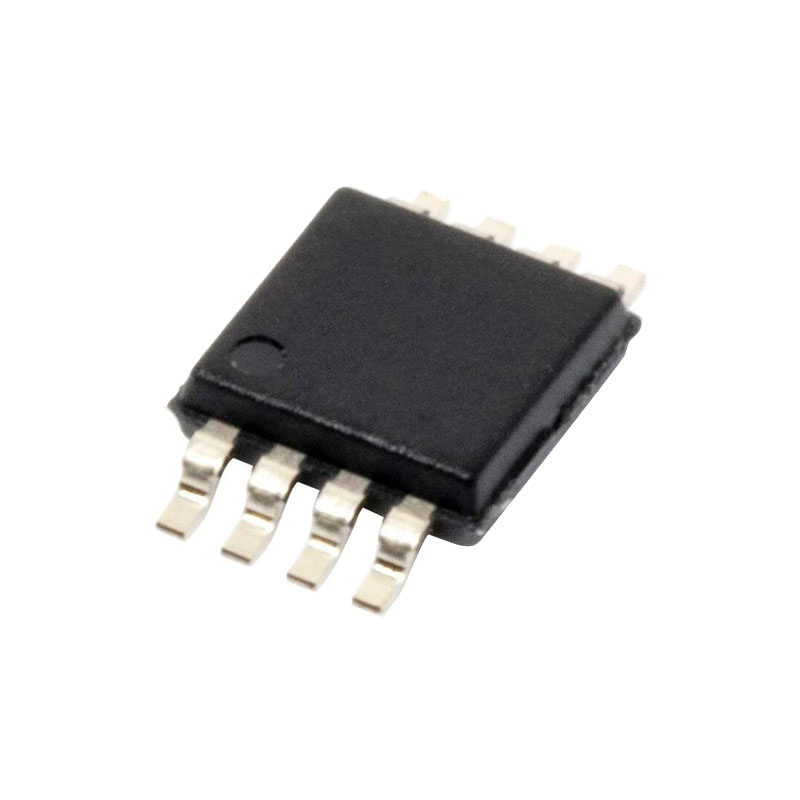
8-Pin μSOP Package
Detailed Description
The Block Diagram shows the relationships between the major function blocks of the DS28EA00. The device has three main data components: 64-bit registration number, 64-bit scratchpad, and alarm and configuration registers. The 1-Wire ROM function control unit processes the ROM function commands that allow the device to function in a networked environment. The device function control unit implements the device-specific control functions, such as read/write, temperature conversion, setting the chain state for sequence detection, and PIO access. The cyclic redundancy check (CRC) generator assists the master verifying data integrity when reading temperatures and memory data. In the sequence-detect process, PIOB functions as an input, while PIOA provides the connection to the next device. The power-supply sensor allows the master to remotely read whether the DS28EA00 has local power available.
64-Bit Registration Number
Each DS28EA00 contains a unique registration number that is 64 bits long. The first 8 bits are a 1-Wire family code. The next 48 bits are a unique serial number. The last 8 bits are a CRC of the first 56 bits. The 1-Wire CRC is generated using a polynomial generator consisting of a shift register and XOR gates. The polynomial is X8 + X5 + X4 + 1. Additional information about the 1-Wire CRC is available in Application Note 27: Understanding and Using Cyclic Redundancy Checks with Maxim iButton® Products.
The shift register bits are initialized to 0. Then starting with the least significant bit of the family code, one bit at a time is shifted in. After the eighth bit of the family code has been entered, then the 48-bit serial number is entered. After the last byte of the serial number has been entered, the shift register contains the CRC value. Shifting in the 8 bits of CRC returns the shift register to all 0s.
1-Wire Bus System
The 1-Wire bus is a system that has a single bus master and one or more slaves. In all instances the DS28EA00 is a slave device. The bus master is typically a micro-controller. The discussion of this bus system is broken down into three topics: hardware configuration, transaction sequence, and 1-Wire signaling (signal types and timing). The 1-Wire protocol defines bus transactions in terms of the bus state during specific time slots, which are initiated on the falling edge of sync pulses from the bus master.


