Beschreibung:
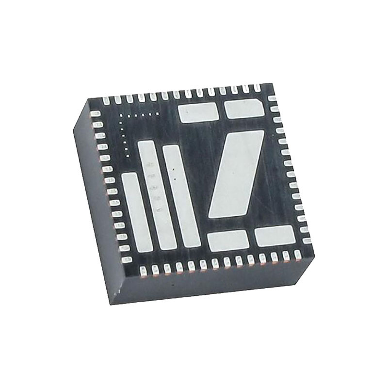
Der EN6362QI ist ein Power System on a Chip (PowerSoC) DC/DC-Wandler mit integrierter Induktivität, PWM-Controller, MOSFETs und Kompensation, der die kleinste Lösung in einem 8x8x3mm großen 56-poligen QFN-Modul darstellt.
Er bietet einen sehr hohen Wirkungsgrad und ist in der Lage, 6A Dauerausgangsstrom ohne De-Rating zu liefern. Der EN6362QI bietet außerdem eine hervorragende Netz- und Lastregelung über die Temperatur. Der EN6362QI wurde speziell für die präzisen Spannungs- und schnellen Transientenanforderungen von Hochleistungsprozessoren, DSP, FPGA, Speicherboards und Anwendungen auf Systemebene in verteilten Stromversorgungsarchitekturen entwickelt.
Zu den weiteren Merkmalen gehören eine präzise Freigabeschwelle, ein monotoner Start vor dem Start und ein programmierbarer Softstart.
Die fortschrittlichen Schaltungstechniken, die ultrahohe Schaltfrequenz und die proprietäre integrierte Induktivitätstechnologie des Geräts sorgen für eine hochwertige, ultrakompakte DC/DC-Wandlung.
Die integrierte Induktionslösung von Altera Enpirion trägt erheblich zur Rauschreduzierung bei. Die Komplettlösung für Leistungswandler steigert die Produktivität, da sie das Design, das Layout und die Fertigungsanforderungen auf der Leiterplatte erheblich vereinfacht.
Eigenschaften:
Hoher Wirkungsgrad (bis zu 96%)
Ausgezeichnete Restwelligkeit und EMI-Leistung
Bis zu 6A kontinuierlicher Betriebsstrom
Eingangsspannungsbereich (3.0V bis 6.5V)
1.5% VFB-Genauigkeit
Optimierte Gesamtgröße der Lösung (160 mm2)
Schwellenwert für die Sequenzierung aktivieren
Programmierbarer Soft-Start
Pin-kompatibel mit dem 8A EN6382QI
Thermischer Schutz, Überstromschutz, Kurzschlussschutz, Rückstrombegrenzung und Unterspannungsschutz
RoHS-konform, MSL Stufe 3, 260°C Reflow
Anwendungen:
Lastpunktregelung für FPGAs, ASICs, Prozessoren, DSPs und verteilte Leistung
Architekturen.
Industrielle Automatisierung, Server, Speicher, Adapterkarten, drahtlose Basisstationen, Test- und Messgeräte und Embedded Computing.
Platzbeschränkte Anwendungen, die die höchste Leistungsdichte erfordern.
Geräuschempfindliche Anwendungen.
Funktionelle Beschreibung
Das EN6362QI ist ein synchrones Abwärtsschaltnetzteil mit integrierten Leistungs-MOSFET-Schaltern und integrierter Drossel. Das Schaltnetzteil verwendet eine Spannungsmodussteuerung und eine rauscharme PWM-Topologie. Der nominale Eingangsspannungsbereich beträgt 3,0 - 6,5 Volt. Die Ausgangsspannung wird über ein externes Widerstandsteiler-Netzwerk programmiert. Die Rückkopplungsschleife beinhaltet ein Typ IV Spannungsmodus-Steuerungsdesign. Die Typ IV-Spannungssteuerung maximiert die Bandbreite des Regelkreises und sorgt für eine hervorragende Phasenspanne, um das Einschwingverhalten zu verbessern. Obwohl der EN6362QI einen Dauerausgangsstrom von bis zu 6A über den gesamten Umgebungstemperaturbereich garantiert (thermisches Design), ist der Spitzenstrom, der vor Erreichen von OCP unterstützt wird, wesentlich höher und übersteigt 10A. Die Betriebsschaltfrequenz kann über einen externen Widerstand zwischen 0,7MHz und 1,7MHz eingestellt werden. Die hohe Schaltfrequenz ermöglicht die Verwendung von kleinen Eingangs- und Ausgangskondensatoren.
Die elektrischen Eigenschaften der EN6362QI auf einen Blick:
- Schwellenwert für Präzision aktivieren
- Soft-Start
- Pre-bias Start-Up
- Widerstand Programmierbare Schaltfrequenz
- Leistung Gut
- Überstrom-/Kurzschlussschutz
- Rückwärtsstrombegrenzung (RCL)
- Thermische Abschaltung (OTP) mit Hysterese
- Unterspannungssperre
Präzision Aktivieren;
Bei der ENABLE-Schwelle handelt es sich um eine analoge Präzisionsspannung und nicht um eine digitale Logikschwelle. Eine Präzisions-Spannungsreferenz und eine Komparatorschaltung werden auch dann mit Strom versorgt, wenn ENABLE deaktiviert ist. Die schmale Spannungslücke zwischen ENABLE Logic Low und ENABLE Logic High (etwa 100mV Hysterese) ermöglicht es dem Baustein, sich bei einem präzisen Enable-Spannungspegel einzuschalten. Der präzise Enable-Schwellenwert ermöglicht in Verbindung mit der richtigen Wahl der Soft-Start-Kondensatoren eine genaue Sequenzierung für mehrere Stromversorgungen. ENABLE hat eine Sperrzeit von 2ms, die verhindert, dass der Baustein sofort nach der Deaktivierung wieder aktiviert wird.
Soft-Start
Der SS-Pin sorgt in Verbindung mit einem kleinen externen Kondensator zwischen diesem Pin und AGND für die Soft-Start-Funktion, die zur Begrenzung des Einschaltstroms während des Starts dient. Wenn das Bauteil aktiviert ist, lädt der Soft-Start (SS)-Stromgenerator den SS-Kondensator auf lineare Weise auf. Solange der SS-Spannungspegel kleiner ist als die Rückkopplungsreferenz (ca. 0,6 V), wird die SS-Spannung als Rückkopplungsreferenz verwendet und sorgt für einen linearen Anstieg der Ausgangsspannung. Sobald die Spannung am SS-Kondensator 0,6 V erreicht, wählt der Minimum-Detektor (Abbildung 20) die Bandgap-Referenz als Ziel, während die Spannung am SS-Kondensator weiter ansteigt, bis sie etwa 1,5 V erreicht. Da die Anstiegsrate der SS-Spannung vom SS-Kondensator abhängt, gilt dies auch für die Ausgangsspannung. Die Anstiegszeit ist definiert als die Zeit, die die Ausgangsspannung benötigt, um von Null auf 95% des programmierten Wertes zu steigen. Die Anstiegszeit (tRISE) ergibt sich aus der folgenden Gleichung: tRISE [ms] = Css [nF] x 0,065 Für den Wert des SS-Kondensators gibt es keine Einschränkungen, aber der übliche Bereich liegt zwischen 10nF und 100nF.
Widerstand Programmierbare Frequenz
Der Betrieb des EN6362QI kann durch eine geeignete Wahl des RFQADJ-Widerstands optimiert werden. Wenn ein hoher Wirkungsgrad der wichtigste Faktor ist, sollte eine niedrigere Schaltfrequenz gewählt werden, während, wenn ein besseres Einschwingverhalten der wichtigste Faktor ist, eine höhere Schaltfrequenz gewählt werden sollte.

