ALLGEMEINE BESCHREIBUNG
The AD7091R-2/AD7091R-4/AD7091R-8 family is a multi channel 12-bit, ultralow power, successive approximation analog-to-digital converter (ADC) that is available in two, four, or eight analog input channel options. The AD7091R-2/AD7091R-4/AD7091R-8 operate from a single 2.7V to 5.25 V power supply and are capable of achieving a sampling rate of 1 MSPS. The AD7091R-2/AD7091R-4/AD7091R-8 family offers up to eight single-ended analog input channels with a channel sequencer that allows a preprogrammed selection of channels to be converted sequentially. The AD7091R-2/AD7091R-4/AD7091R-8 also feature an on-chip conversion clock, an on-chip accurate 2.5 V reference, and a high speed serial interface. The AD7091R-2/AD7091R-4/AD7091R-8 have a serial port interface (SPI) that allows data to be read after the conversion while achieving a 1 MSPS throughput rate. The conversion process and data acquisition are controlled using the CONVST pin. The AD7091R-2/AD7091R-4/AD7091R-8 use advanced design techniques to achieve ultralow power dissipation at high throughput rates. They also feature flexible power management options. An on-chip configuration register allows the user to set up different operating conditions. These include power management, alert functionality, busy indication, channel sequencing, and general-purpose output pins. The MUXOUT and ADCIN pins allow signal conditioning of the multiplexer output prior to acquisition by the ADC.
FEATURES
Ultralow system power
Flexible power/throughput rate management
Normal mode
1.4 mW at 1 MSPS
Power-down mode
550 nA typical at VDD = 5.25 V
435 nA typical at VDD = 3 V
Programmable ALERT interrupt pin (4-/8-channel models)
Hohe Leistung
1 MSPS throughput with no latency/pipeline delay
SNR: 70 dB typical at 10 kHz input frequency
THD: −80 dB typical at 10 kHz input frequency
INL: ±0.7 LSB typical, ±1.0 LSB maximum
Small system footprint
On-chip accurate 2.5 V reference, 5 ppm/°C typical drift
MUXOUT/ADCIN to allow single buffer amplifier
Daisy-chain mode
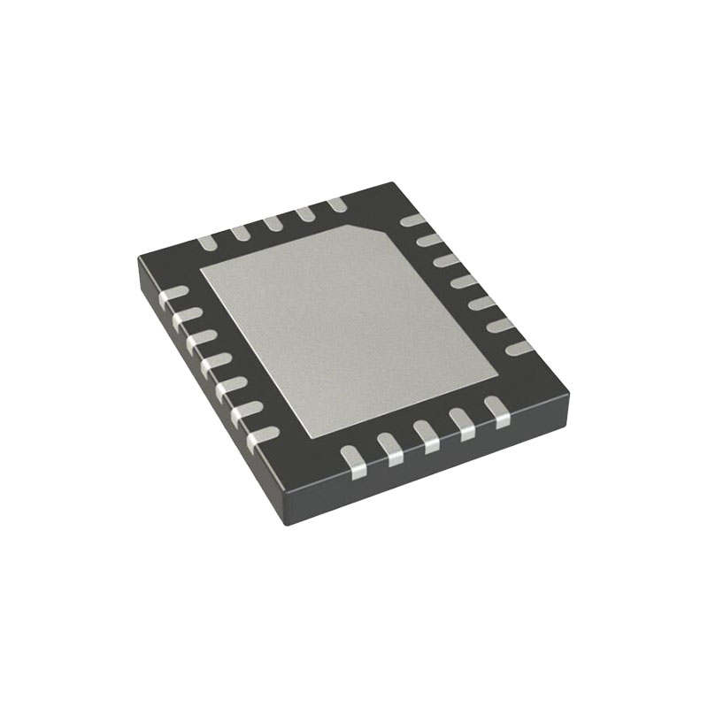
16-lead, 20-lead, and 24-lead 4 mm × 4 mm LFCSP packages
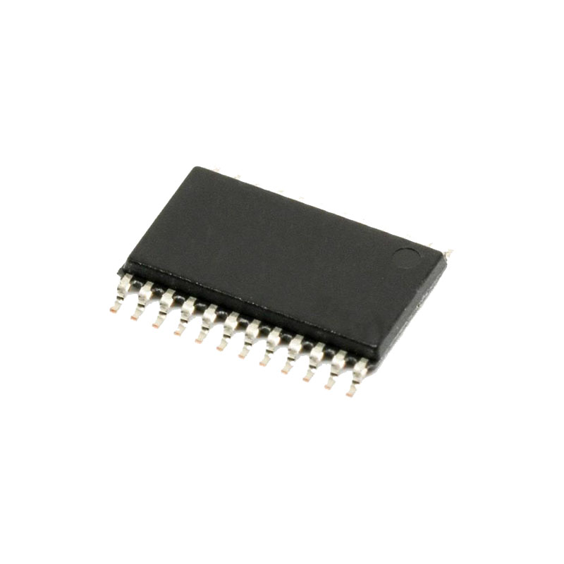
16-lead, 20-lead, and 24-lead TSSOP packages
Easy to use
SPI/QSPI™/MICROWIRE™/DSP compatible digital interface
Integrated programmable channel sequencer
BUSY indication available (4-/8-channel models)
Built in features for control and monitoring applications
GPOx pins available (4-/8-channel models)
Wide operating range
Temperature range: −40°C to +125°C
Specified for VDD of 2.7 V to 5.25 V
ANWENDUNGEN
Battery-powered systems
Persönliche digitale Assistenten
Medizinische Instrumente
Mobile communications
Instrumentation and control systems
Data acquisition systems
Optical sensors
Diagnostic/monitoring functions
ARBEITSTHEORIE
CIRCUIT INFORMATION
The AD7091R-2/AD7091R-4/AD7091R-8 are 12-bit, fast (1 MSPS),ultralow power, single-supply ADCs. The devices operate from a 2.7 V to 5.25 V supply. The AD7091R-2/AD7091R-4/AD7091R-8 are capable of throughput rates of 1 MSPS. The AD7091R-2/AD7091R-4/AD7091R-8 provide an on-chip, trackand-hold ADC and a serial interface housed in a 16-lead, 20lead, or 24-lead TSSOP or LFCSP package, which offers considerable space-saving advantages over alternative solutions. The serial clock input accesses data from the device. The clock for the successive approximation ADC is generated internally. The reference voltage for the AD7091R-2/AD7091R-4/AD7091R-8 is provided externally, or it is generated internally by an accurate onchip reference source. The analog input range for the AD7091R-2/ AD7091R-4/AD7091R-8 is 0 V to VREF. The AD7091R-2/AD7091R-4/AD7091R-8 also feature a powerdown option to save power between conversions. The power-down feature is implemented across the standard serial interface as described in the Modes of Operation section.
REFERENCE
The AD7091R-2/AD7091R-4/AD7091R-8 can operate with either the internal 2.5 V on-chip reference or an externally applied reference. The logic state of the P_DOWN LSB bit in the configuration register determines whether the internal reference is used. The internal reference is selected for the ADCs when the P_DOWN LSB bit is set to 1. When the P_DOWN LSB bit is set to 0, supply an external reference in the range of 1.0 V to VDD through the REFIN/REFOUT pin. At power-up, the internal reference disables by default. The internal reference circuitry consists of a 2.5 V band gap reference and a reference buffer. When operating the AD7091R-2/ AD7091R-4/AD7091R-8 in internal reference mode, the 2.5 V internal reference is available at the REFIN/REFOUT pin, which is typically decoupled to GND using a 2.2 µF capacitor. It is recommended to buffer the internal reference before applying it elsewhere in the system. The reference buffer requires 50 ms to power up and charge the 2.2 µF decoupling capacitor during the power-up time.