Beschreibung
The LTC3851A-1 is a high performance synchronous step-down switching regulator controller that drives an all N-channel synchronous power MOSFET stage. A con stant frequency current mode architecture allows a phase-lockable frequency of up to 750kHz. OPTI-LOOP compensation allows the transient response to be optimized over a wide range of output capacitance and ESR values. The LTC3851A-1 features a precision 0.8V reference and a power good indicator. A wide 4V to 38V (40V absolute maximum) input supply range encompasses most battery configurations and intermediate bus voltages. The TK/SS pin ramps the output voltage during start-up and shutdown with coincident or ratiometric tracking. Current foldback limits MOSFET heat dissipation during shortcircuit conditions. The MODE/PLLIN pin selects among Burst Mode operation, pulse-skipping mode or continuous inductor current mode at light loads and allows the IC to be synchronized to an external clock. The LTC3851A-1 contains an improved PLL compared to the LTC3851-1. The LTC3851A-1 is identical to the LTC3851A except that the ILIM pin is replaced by PGOOD.
Eigenschaften
Wide VIN Range: 4V to 38V Operation
RSENSE or DCR Current Sensing
±1% Genauigkeit der Ausgangsspannung
Power Good Output Voltage Monitor
Phase-Lockable Fixed Frequency: 250kHz to 750kHz
Dual N-Channel MOSFET Synchronous Drive
Very Low Dropout Operation: 99% Duty Cycle
Adjustable Output Voltage Soft-Start or Tracking
Output Current Foldback Limiting
Überspannungsschutz am Ausgang
OPTI-LOOP® Compensation Minimizes COUT
Selectable Continuous, Pulse-Skipping or Burst Mode® Operation at Light Loads
Low Shutdown IQ: 20µA
VOUT Range: 0.8V to 5.5V
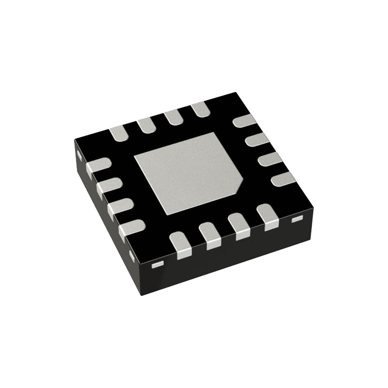
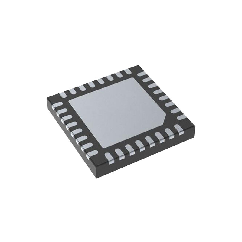
Thermally Enhanced 16-Lead MSOP or 3mm × 3mm QFN Package
Anwendungen
Automobile Systeme
Telecom Systems
Industrielle Ausrüstung
Distributed DC Power Systems
Applications information
The Typical Application on the first page of this data sheet is a basic LTC3851A-1 application circuit. The LTC3851A-1 can be configured to use either DCR (inductor resistance) sensing or low value resistor sensing. The choice of the two current sensing schemes is largely a design trade-off between cost, power consumption and accuracy. DCR sensing is becoming popular because it saves expensive current sensing resis tors and is more power efficient, especially in high current applications. However, current sensing resistors provide the most accurate current limits for the controller. Other external component selection is driven by the load require ment, and begins with the selection of RSENSE (if RSENSE is used) and the inductor value. Next, the power MOSFETs and Schottky diodes are selected. Finally, input and output capacitors are selected. The circuit shown on the first page can be configured for operation up to 38V at VIN.
SENSE+ and SENSE– Pins
The SENSE+ and SENSE– pins are the inputs to the current comparators. The common mode input voltage range of the current comparators is 0V to 5.5V. Both SENSE pins are high impedance inputs with small base currents of less than 1μA. When the SENSE pins ramp up from 0V to 1.4V, the small base currents flow out of the SENSE pins. When the SENSE pins ramp down from 5V to 1.1V, the small base currents flow into the SENSE pins. The high impedance inputs to the current comparators allow accurate DCR sensing. However, care must be taken not to float these pins during normal operation.
Inductor DCR Sensing
For applications requiring the highest possible efficiency, the LTC3851A-1 is capable of sensing the voltage drop across the inductor DCR, as shown in Figure 2. The DCR of the inductor represents the small amount of DC winding resis tance of the copper, which can be less than 1mΩ for today’s low value, high current inductors. If the external R1||R2 • C1 time constant is chosen to be exactly equal to the L/DCR time constant, the voltage drop across the external capacitor is equal to the voltage drop across the inductor DCR multiplied by R2/(R1 + R2). Therefore, R2 may be used to scale the voltage across the sense terminals when the DCR is greater than the target sense resistance. Check the manufacturer’s data sheet for specifications regarding the inductor DCR, in order to properly dimension the external filter components. The DCR of the inductor can also be measured using a good RLC meter.


