Allgemeine Beschreibung
The MAX3646 is a +3.3V laser driver designed for multirate transceiver modules with data rates from 155Mbps to 622Mbps. Lasers can be DC-coupled to the MAX3646 for reduced component count and ease of multirate operation.
Laser extinction ratio control (ERC) combines the features of automatic power control (APC), modulation compensation, and built-in thermal compensation. The APC loop maintains constant average optical power. Modulation compensation increases the modulation current in proportion to the bias current. These control loops, combined with thermal compensation, maintain a constant optical extinction ratio over temperature and lifetime.
The MAX3646 accepts differential data input signals. The wide 5mA to 60mA (up to 85mA AC-coupled) modulation current range and up to 100mA bias current range, make the MAX3646 ideal for driving FP/DFB lasers in fiber optic modules. External resistors set the required laser current levels. The MAX3646 provides transmit disable control (TX_DISABLE), single-point fault tolerance, bias-current monitoring, and photocurrent monitoring. The device also offers a latched failure output (TX_FAULT) to indicate faults, such as when the APC loop is no longer able to maintain the average optical power at the required level. The MAX3646 is compliant with the SFF-8472 transmitter diagnostic and SFP MSA timing requirements.
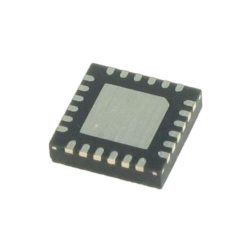
The MAX3646 is offered in a 4mm x 4mm, 24-pin thin QFN package and operates over the extended -40°C to +85°C temperature range.
Anwendungen
Multirate OC-3 to OC-12 FEC Transceivers
125Mbps Ethernet SFP, GBIC, and 1 x 9
Transceivers
Eigenschaften
Single +3.3V Power Supply
47mA Power-Supply Current
85mA Modulation Current
100mA Bias Current
Automatic Power Control (APC)
Modulation Compensation
On-Chip Temperature Compensation
Self-Biased Inputs for AC-Coupling
Ground-Referenced Current Monitors
Laser Shutdown and Alarm Outputs
Enable Control and Laser Safety Feature
Detaillierte Beschreibung
The MAX3646 laser driver consists of three main parts: a high-speed modulation driver, biasing block with ERC, and safety circuitry. The circuit design is optimized for high-speed, low-voltage (+3.3V) operation.
High-Speed Modulation Driver
The output stage is composed of a high-speed differential pair and a programmable modulation current source. The MAX3646 is optimized for driving a 15Ω load. The minimum instantaneous voltage required at OUT- is 0.7V for modulation currents up to 60mA and 0.75V for currents from 60mA to 85mA. Operation above 60mA can be accomplished by AC-coupling or with sufficient voltage at the laser to meet the driver output voltage requirement.
To interface with the laser diode, a damping resistor (RD) is required. The combined resistance damping resistor and the equivalent series resistance (ESR) of the laser diode should equal 15Ω. To further damp aberrations caused by laser diode parasitic inductance, an RC shunt network may be necessary. Refer to Application Note 274: HFAN-02.0: Interfacing Maxim Laser Drivers with Laser Diodes for more information.
Any capacitive load at the cathode of a laser diode degrades optical output performance. Because the BIAS output is directly connected to the laser cathode, minimize the parasitic capacitance associated with the pin by using an inductor to isolate the BIAS pin parasitics form the laser cathode.
Design Procedure
When designing a laser transmitter, the optical output is usually expressed in terms of average power and extinction ratio.Shows relationships that are helpful in converting between the optical average power and the modulation current. These relationships are valid if the mark density and duty cycle of the optical waveform are 50%.
For a desired laser average optical power (PAVG) and optical extinction ratio (re), the required bias and modulation currents can be calculated using the equations. Proper setting of these currents requires knowledge of the laser to monitor transfer (ρMON) and slope efficiency (η).
Layout Considerations
To minimize loss and crosstalk, keep the connections between the MAX3646 output and the laser diode as short as possible. Use good high-frequency layout techniques and multilayer boards with uninterrupted ground plane to minimize EMI and crosstalk. Circuit boards should be made using low-loss dielectrics. Use controlled-impedance lines for data inputs, as well as the module output.


