Allgemeine Beschreibung
The MAX8520/MAX8521 are designed to drive thermoelectric coolers (TECs) in space-constrained optical modules. Both devices deliver ±1.5A output current and control the TEC current to eliminate harmful current surges. On-chip FETs minimize external components and high switching frequency reduces the size of external components.
The MAX8520/MAX8521 operate from a single supply and bias the TEC between the outputs of two synchronous buck regulators. This operation allows for temperature control without “dead zones” or other nonlinearities at low current. This arrangement ensures that the control system does not hunt when the set-point is very close to the natural operating point, requiring a small amount of heating or cooling. An analog control signal precisely sets the TEC current.
Both devices feature accurate, individually-adjustable heating current limit and cooling current limit along with maximum TEC voltage limit to improve the reliability of optical modules. An analog output signal monitors theTEC current. A unique ripple cancellation scheme helps reduce noise.
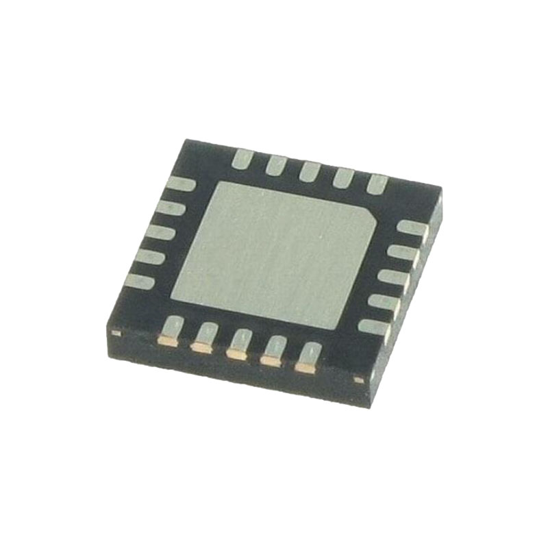
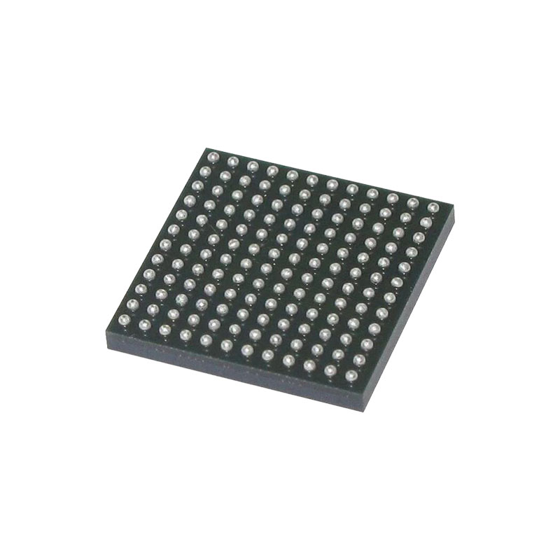
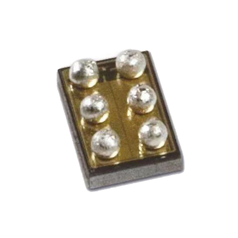
The MAX8521 is available in a 5mm x 5mm TQFN as well as space-saving 3mm x 3mm UCSP™ and 36-bump WLP (3mm x 3mm) packages, with a pin-selectable switching frequency of 500kHz or 1MHz.
Anwendungen
SFF/SFP Modules
Fiber Optic Laser Modules
Fiber Optic Network Equipment
ATE
Biotech Lab Equipment
Eigenschaften
Circuit Footprint 0.31in²
Low Profile Design
On-Chip Power MOSFETs
High-Efficiency Switch-Mode Design
Ripple Cancellation for Low Noise
Direct Current Control Prevents TEC Current Surges
5% Accurate Adjustable Heating/Cooling Current Limits
2% Accurate TEC Voltage Limit
No Dead Zone or Hunting at Low Output Current
ITEC Monitors TEC Current
1% Accurate Voltage Reference
Switching Frequency up to 1MHz
Synchronization (MAX8521)
Detaillierte Beschreibung
The MAX8520/MAX8521 TEC drivers consist of two switching buck regulators that operate together to directly control the TEC current. This configuration creates a differential voltage across the TEC, allowing bidirectional TEC current for controlled cooling and heating. Controlled cooling and heating allow accurate TEC temperature control to within 0.01°C. The voltage at CTLI directly sets the TEC current. An external thermalcontrol loop is typically used to drive CTLI.
Ripple Cancellation
Switching regulators like those used in the MAX8520/MAX8521 inherently create ripple voltage on the output. The dual regulators in the MAX8520/MAX8521 switch in-phase and provide complementary in-phase duty cycles so ripple waveforms at the TEC are greatly reduced. This feature suppresses ripple currents and electrical noise at the TEC to prevent interference with the laser diode.
Thermal and Fault-Current Protection
The MAX8520/MAX8521 provide fault-current protection in either FETs by turning off both high-side and low-side FETs when the peak current exceeds 3A in either FETs. In addition, thermal-overload protection limits the total power dissipation in the chip. When the device’s die junction temperature exceeds +165°C, an on-chip thermal sensor shuts down the device. The thermal sensor turns the device on again after the junction temperature cools down by +15°C.
Inductor Selection
The MAX8520/MAX8521 dual buck converters operate in-phase and in complementary mode to drive the TEC differentially in a current-mode control scheme. At zero TEC current, the differential voltage is zero, hence the outputs with respect to GND are equal to half of VDD.
For a given inductor, and input voltage, the maximum inductor ripple current happens when the duty cycle is at 50%. Therefore, the inductor should be calculated at 50% duty cycle to find the maximum ripple current. The maximum desired ripple current of a typical standard buck converter is in the range of 20% to 40% of the maximum load. The higher the value of the inductor, the lower the ripple current. However, the size will be physically larger. For the TEC driver the thermal loop is inherently slow, so the inductor can be larger for lower ripple current for better noise and EMI performance. Picking an inductor to yield ripple current of 10% to 20% of the maximum TEC current is a good starting point.
Setting Voltage and Current Limits
Certain TEC parameters must be considered to guarantee a robust design. These include maximum positive current, maximum negative current, and the maximum voltage allowed across the TEC. These limits should be used to set the MAXIP, MAXIN, and MAXV voltages.


