BESCHREIBUNG
The OPA564 is a low-cost, high-current operational amplifier that is ideal for driving up to 1.5A into reactive loads. The high slew rate provides 1.3MHz full-power bandwidth and excellent linearity. These monolithic integrated circuits provide high reliability in demanding powerline communications and motor control applications.
The OPA564 operates from a single supply of 7V to 24V, or dual power supplies of ±3.5V to ±12V. In single-supply operation, the input common-mode range extends to the negative supply. At maximum output current, a wide output swing provides a 20VPP (IOUT = 1.5A) capability with a nominal 24V supply.
The OPA564 is internally protected against over-temperature conditions and current overloads. It is designed to provide an accurate, user-selected current limit. Two flag outputs are provided; one indicates current limit and the second shows a thermal over-temperature condition. It also has an Enable/Shutdown pin that can be forced low to shut down the output, effectively disconnecting the load.
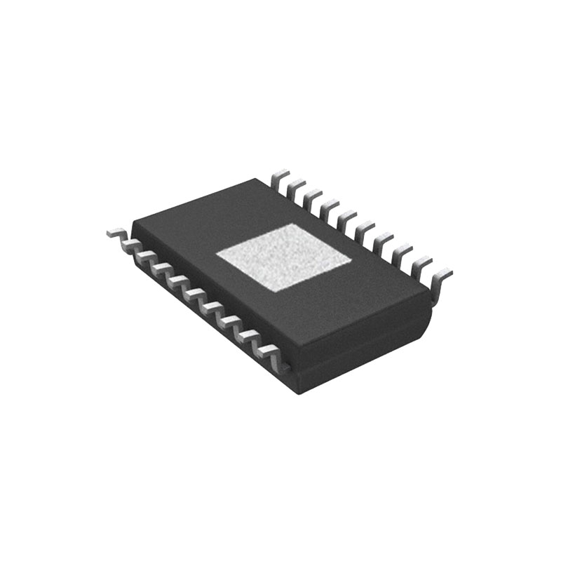
The OPA564 is housed in a thermally-enhanced, surface-mount PowerPAD™ package (HSOP-20) with the choice of the thermal pad on either the top side or the bottom side of the package. Operation for both versions is specified over the industrial temperature range,–40°C to +85°C.
FEATURES
• HIGHOUTPUTCURRENT: 1.5A
• WIDEPOWER-SUPPLY RANGE:
– Single Supply: +7V to +24V
– Dual Supply: ±3.5V to ±12V
• LARGEOUTPUTSWING: 20VPP at 1.5A
• FULLYPROTECTED:
– THERMALSHUTDOWN
– ADJUSTABLE CURRENT LIMIT
• DIAGNOSTIC FLAGS:
– OVER-CURRENT
– THERMALSHUTDOWN
• OUTPUTENABLE/SHUTDOWNCONTROL
• HIGHSPEED:
– GAIN-BANDWIDTH PRODUCT: 17MHz
– FULL-POWER BANDWIDTH AT 10VPP:1.3MHz
– SLEWRATE:40V/ms
• DIODEFORJUNCTION TEMPERATURE MONITORING
• HSOP-20 PowerPAD™ PACKAGE
(Bottom- and Top-Side Thermal Pad Versions)
ANWENDUNGEN
• POWERLINECOMMUNICATIONS
• VALVE, ACTUATOR DRIVER
• VCOMDRIVER
• MOTORDRIVER
• AUDIOPOWERAMPLIFIER
• POWER-SUPPLY OUTPUT AMPLIFIER
• TESTEQUIPMENT AMPLIFIER
• TRANSDUCEREXCITATION
• LASERDIODEDRIVER
• GENERAL-PURPOSE LINEAR POWERBOOSTER
CURRENT LIMIT FLAG
The OPA564 features a current limit flag (IFLAG) that can be monitored to determine if the load current is operating within or exceeding the current limit set by the user. The output signal of IFLAG is compatible with standard CMOS logic and is referenced to the negative supply pin (V–). A voltage level of + 0.8V or less with respect to V– indicates that the amplifier is operating within the limits set by the user. A voltage level of +2.0V or greater with respect to V– indicates that the OPA564 is operating above (exceeds) the current limit set by the user. See Setting the Current Limit for proper current limit operation.
OUTPUT STAGE COMPENSATION
The complex load impedances common in power op amp applications can cause output stage instability. For normal operation, output compensation circuitry is typically not required. However, if the OPA564 is intended to be driven into current limit, an R/C network (snubber) may be required. Typically, 3Ω to 10Ω in series with 0.01mF to 0.1mF is adequate. Some variations in circuit value may be required with certain loads.
THERMAL PROTECTION
The OPA564 has thermal sensing circuitry that helps protect the amplifier from exceeding temperature limits. Power dissipated in the OPA564 causes the junction temperature to rise. Internal thermal shutdown circuitry disables the output when the die temperature reaches the thermal shutdown temperature limit. The OPA564 output remains shut down until the die has cooled sufficiently; see the Electrical Characteristics, Thermal Shutdown section.
Depending on load and signal conditions, the thermal protection circuit may cycle on and off. This cycling limits the amplifier dissipation, but may have undesirable effects on the load. Any tendency to activate the thermal protection circuit indicates excessive power dissipation or an inadequate heatsink. For reliable, long-term, continuous operation, with IOUT at the maximum output of 1.5A, the junction temperature should be limited to +85°C maximum. The internal protection circuitry of the OPA564 was designed to protect against overload conditions; it was not intended to replace proper heatsinking. Continuously running the OPA564 into thermal shutdown degrades reliability.