Descripción
The LM124, LM224x and LM324x consist of four independent, high gain operational amplifiers with frequency compensation implemented internally. They operate from a single power supply over a wide range of voltages.
Operation from split power supplies is also possible and the low-power supply current drain is independent of the magnitude of the power supply voltage.
Características
• Wide gain bandwidth: 1.3 MHz
• Input common mode voltage range includes ground
• Large voltage gain: 100 dB
• Very low supply current/amplifier: 375 µA
• Low input bias current: 20 nA
• Low input voltage: 3 mV max.
• Low input offset current: 2 nA
• Wide power supply range:
– Single supply: 3 V to 30 V
– Dual supplies: ±1.5 V to ±15 V Related products
• See TSB572 and TSB611, 36 V newer technology devices, which have enhanced accuracy and ESD rating, reduced power consumption, and automotive grade qualification
• See LM2902 and LM2902W for automotive grade applications
Absolute maximum ratings and operating conditions
1. Neither of the input voltages must exceed the magnitude of (VCC +) or (VCC -).
2. Short-circuits from the output to VCC can cause excessive heating if VCC > 15 V. The maximum output current is approximately 40 mA independent of the magnitude of VCC. Destructive dissipation can result from simultaneous short-circuits on all amplifiers.
3. This input current only exists when the voltage at any of the input leads is driven negative. It is due to the collector-base junction of the input PNP transistor becoming forward biased and thereby acting as an input diode clamp. In addition to this diode action, there is also an NPN parasitic action on the IC chip. This transistor action can cause the output voltages of the op amps to go to the VCC voltage level (or to ground for a large overdrive) for the time during which an input is driven negative. This is not destructive and normal output starts up again for input voltages higher than -0.3 V.
4. Short-circuits can cause excessive heating. Destructive dissipation can result from simultaneous short circuits on all amplifiers. These are typical values given for a single layer board (except for TSSOP which is a two-layer board).
5. Human body model: 100pF discharged through a 1.5kΩ resistor between two pins of the device, done for all couples of pin combinations with other pins floating.
6. Machine model: a 200pF cap is charged to the specified voltage, then discharged directly between two pins of the device with no external series resistor (internal resistor < 5 Ω), done for all couples of pin combinations with other pins floating.
Electrical characteristics
1. Vo = 1.4 V, Rs = 0 Ω, 5 V < VCC + < 30 V, 0 < Vic < VCC + – 1.5 V
2. The direction of the input current is out of the IC. This current is essentially constant, independent of the state of the output so there is no load change on the input lines.
3. The input common-mode voltage of either input signal voltage should not be allowed to go negative by more than 0.3 V. The upper end of the common-mode voltage range is (VCC +) – 1.5 V, but either or both inputs can go to 32 V without damage.
4. Due to the proximity of external components, ensure that there is no coupling originating from stray capacitance between these external parts. Typically, this can be detected at higher frequencies because this type of capacitance increases.
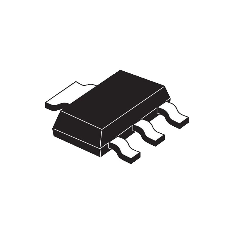
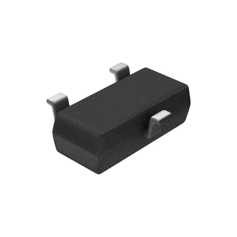
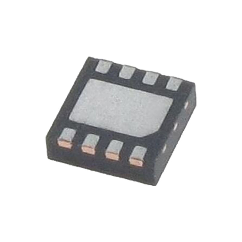
Package information
In order to meet environmental requirements, ST offers these devices in different grades of ECOPACK packages, depending on their level of environmental compliance. ECOPACK specifications, grade definitions and product status are available at: www.st.com. ECOPACK is an ST trademark.For more details, please refer to the specification sheet.