DESCRIPCIÓN GENERAL
The ADMV8818-EP is a fully monolithic microwave integrated circuit (MMIC) that features a digitally selectable frequency of operation. The device features four independently controlled highpass filters (HPFs) and four independently controlled low-pass filters (LPFs) that span the 2 GHz to 18 GHz frequency range.
The flexible architecture of the ADMV8818-EP allows the 3 dB cutoff frequency (f3dB) of the high-pass and low-pass filters to be controlled independently to generate up to 4 GHz of bandwidth.
The digital logic control on each filter is 4 bits wide (16 states) and controls the on-chip reactive elements to adjust the f3dB. The typical insertion loss is 9 dB, and the wideband rejection is 35 dB, which is ideally suited for minimizing system harmonics.
This tunable filter can be used as a smaller alternative to large switched filter banks and cavity tuned filters, and this device provides a dynamically adjustable solution in advanced communications applications.
CARACTERÍSTICAS
Digitally tunable, multioctave, high-pass and low-pass tuning
Independent 3 dB frequency control for up to 4 GHz of bandwidth
Optimal wideband rejection: 35 dB
Single chip replacement for discrete filter banks
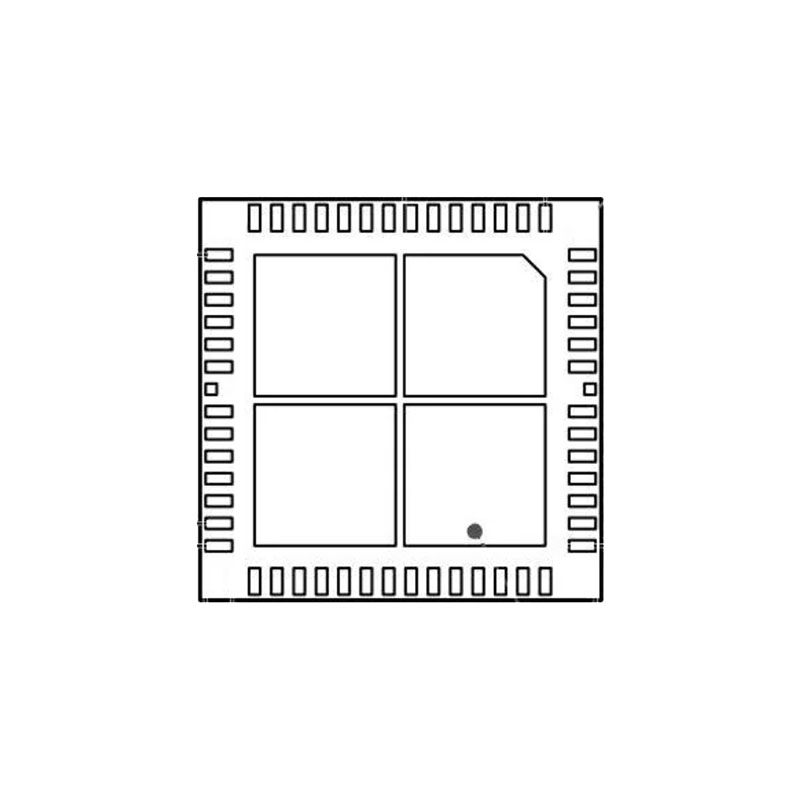
Compact 9 mm × 9 mm, 56-terminal LGA package
ENHANCED PRODUCT FEATURES
Supports defense and aerospace applications (AQEC standard)
Military temperature range of −55°C to +105°C
Controlled manufacturing baseline
One assembly and test site
One fabrication site
Production change notification
Qualification data available on request
APLICACIONES
Test and measurement equipment
Military radar, electronic warfare, and electronic
countermeasures
Satellite communications and space
Industrial and medical equipment
TEORÍA DE FUNCIONAMIENTO
CHIP ARCHITECTURE
The ADMV8818-EP is a highly flexible filter that can achieve tunable band-pass, high-pass, low-pass, all pass, or all reject responses from 2 GHz to 18 GHz. Due to the flexible architecture of the ADMV8818-EP with four SP5T switches coupled with digitally tunable high-pass and low-pass filter arrays, the device provides full coverage over the frequency band without any dead zones.
The ADMV8818-EP consists of two sections, the input and the output section. The input section has four high-pass filters and an optional bypass configuration that is selectable by the two SP5T RFIN switches. Similarly, the output section has four low-pass filters and an optional bypass configuration that is selectable by the two SP5T RFOUT switches. Because the input and output sections are independent from one another, the chip can be configured for any combination of high-pass filter, low-pass filter, or bypass configuration.
The two SP5T RFIN switches are controlled simultaneously with a 3-bit digital control. Likewise, the two SP5T RFOUT switches are controlled simultaneously with a 3-bit digital control. This control scheme creates a total of 25 possible combinations of switch settings, achieving many possible filter responses.
MODE SELECTION
The ADMV8818-EP has two modes of operation: SPI write and SPI fast latch. SPI write mode is the normal operating mode, whereas SPI fast latch mode is used to sequence through the on-chip lookup table (LUT) using the internal state machine. To select SPI write mode, set the SFL pin low. For operation in SPI fast latch mode, program the on-chip lookup table and fast latch parameters with the SFL pin low, and then bring the SFL pin high to enter this mode.
SPI WRITE MODE
SPI write mode has five write groupings, WR0 through WR4 in Register 0x020 through Register 0x029. The groupings can be thought of as a small lookup table for SPI write mode. Each grouping consists of the following:
• RFIN switch position
• RFIN switch set
• RFOUT switch position
• RFOUT switch set
• HPF state
• LPF state
FILTER SETTINGS
Each high-pass filter and low-pass filter contains 16 states (4 bits). A value of zero corresponds to setting the f3dB of the filter to its lowest possible frequency. Conversely, a value of 15 corresponds to setting the f3dB of the filter to its highest possible frequency.