CARACTERÍSTICAS
Outputs May be Paralleled for Higher Current and Heat Spreading
Output Current: 500mA
Programas de una sola resistencia Tensión de salida
1% Initial Accuracy of SET Pin Current
Output Adjustable to 0V
Current Limit Constant with Temperature
Low Output Noise: 40µVRMS (10Hz to 100kHz)
Wide Input Voltage Range: 1.2V to 36V
Low Dropout Voltage: 275mV
< 1mV Load Regulation
< 0.001%/ V Line Regulation
Minimum Load Current: 0.5mA
Stable with Minimum 2.2µF Ceramic Capacitor
Current Limit with Fold back and Over temperature Protected
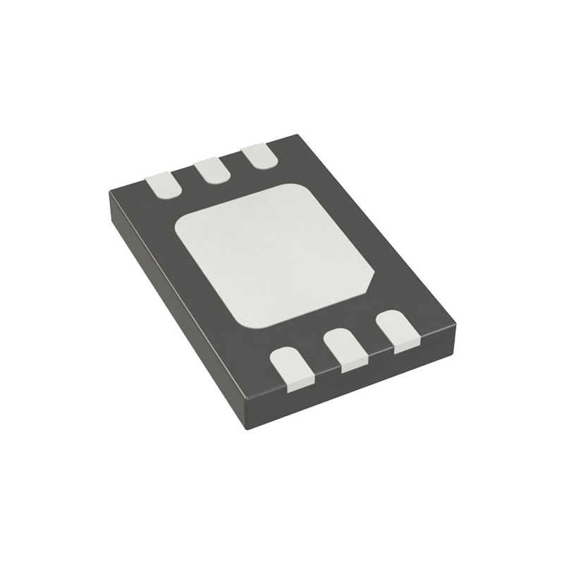
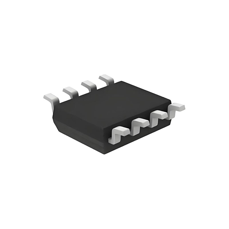
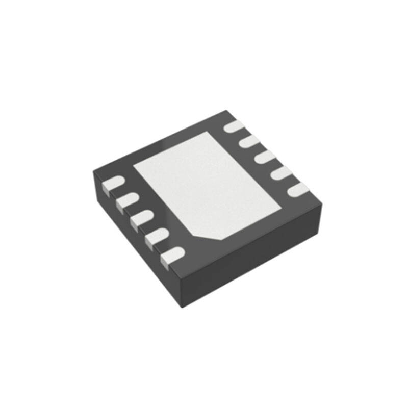
8-Lead MSOP, and 6-Lead 2mm × 3mm DFN Packages
Cualificación AEC-Q100 para aplicaciones de automoción
APLICACIONES
High Current All Surface Mount Supply
High Efficiency Linear Regulator
Post Regulator for Switching Supplies
Low Parts Count Variable Voltage Supply
Low Output Voltage Power Supplies
DESCRIPCIÓN
The LT®3085 is a 500mA low dropout linear regulator that can be paralleled to increase output current or spread heat on surface mounted boards. Designed as a precision current source and voltage follower, this new regulator finds use in many applications requiring high current, adjustability to zero, and no heat sink. The device also brings out the collector of the pass transistor to allow low dropout operation—down to 275mV—when used with a second supply.
A key feature of the LT3085 is the capability to supply a wide output voltage range. By using a reference cur rent through a single resistor, the output voltage is pro grammed to any level between zero and 36V. The LT3085 is stable with 2.2µF of capacitance on the output, and the IC uses small ceramic capacitors that do not require additional ESR as is common with other regulators.
Internal protection circuitry includes current limiting and thermal limiting. The LT3085 is offered in the 8-lead MSOP and a low profile (0.75mm) 6-lead 2mm × 3mm DFN package (both with an Exposed Pad for better ther mal characteristics).
INFORMACIÓN SOBRE APLICACIONES
The LT3085 regulator is easy to use and has all the pro tection features expected in high performance regulators. Included are short-circuit protection and safe operating area protection, as well as thermal shutdown.
The LT3085 is especially well suited to applications needing multiple rails. The new architecture adjusts down to zero with a single resistor, handling modern low voltage digital ICs as well as allowing easy parallel operation and thermal management without heat sinks. Adjusting to “zero” output allows shutting off the powered circuitry and when the input is pre-regulated – such as a 5V or 3.3V input supply – external resistors can help spread the heat.
A precision “0” TC 10µA internal current source is connected to the non-inverting input of a power operational amplifier. The power operational amplifier provides a low impedance buffered output to the voltage on the non-inverting input. A single resistor from the non inverting input to ground sets the output voltage and if this resistor is set to zero, zero output results. As can be seen, any output voltage can be obtained from zero up to the maximum defined by the input power supply.
What is not so obvious from this architecture are the benefits of using a true internal current source as the reference as opposed to a bootstrapped reference in older regulators. A true current source allows the regulator to have gain and frequency response independent of the impedance on the positive input. Older adjustable regulators, such as the LT1086, have a change in loop gain with output voltage as well as bandwidth changes when the adjustment pin is bypassed to ground. For the LT3085, the loop gain is unchanged by changing the out put voltage or bypassing. Output regulation is not fixed at a percentage of the output voltage but is a fixed fraction of millivolts. Use of a true current source allows all the gain in the buffer amplifier to provide regulation and none of that gain is needed to amplify up the reference to a higher output voltage.
The LT3085 has the collector of the output transistor connected to a separate pin from the control input. Since the dropout on the collector (IN pin) is only 275mV, two supplies can be used to power the LT3085 to reduce dissipation: a higher voltage supply for the control circuitry and a lower voltage supply for the collector. This increases efficiency and reduces dissipation. To further spread the heat, a resistor can be inserted in series with the collector to move some of the heat out of the IC and spread it on the PC board.

