DESCRIPCIÓN
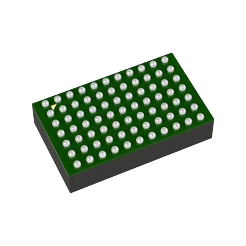
The LTM4644/LTM4644-1 is a quad DC/DC step-down µModule (micromodule) regulator with 4A per output. Outputs can be paralleled in an array for up to 16A capability. Included in the package are the switching controllers, power FETs, inductors and support components. Operating over an input voltage range of 4V to 14V or 2.375V to 14V with an external bias supply, the LTM4644/LTM4644-1 supports an output voltage range of 0.6V to 5.5V. Its high efficiency design delivers 4A continuous (5A peak) output current per channel. Only bulk input and output capacitors are needed.
CARACTERÍSTICAS
Quad Output Step-Down µModule® Regulator with 4A per Output
Amplio rango de tensión de entrada: 4V a 14V
2,375 V a 14 V con polarización externa
0,6 V a 5,5 V Tensión de salida
Corriente de salida de 4 A CC, 5 A de pico por canal
Disipación de potencia de hasta 5,5 W (TA = 60 °C, 200 LFM, sin disipador de calor)
±1,5% Regulación total de la tensión de salida
Control en modo corriente, respuesta transitoria rápida
Paralelable para una mayor corriente de salida
Seguimiento de la tensión de salida
Salida de diodo interno de detección de temperatura
Sincronización de frecuencia externa
Protección contra sobretensión, corriente y temperatura
9 mm × 15 mm × 5,01 mm Paquete BGA
APLICACIONES
Regulación del punto de carga multirraíl
Aplicaciones FPGA, DSP y ASIC
OPERACIÓN
The LTM4644 is a quad output standalone non-isolated switch mode DC/DC power supply. It has four separate regulator channels with each of them capable of delivering up to 4A continuous output current with few external input and output capacitors. Each regulator provides precisely regulated output voltage programmable from 0.6V to 5.5V via a single external resistor (two resistors for LTM4644-1) over 4V to 14V input voltage range. With an external bias voltage, this module can operate from an input voltage as low as 2.375V.
The LTM4644 integrates four separate constant frequency controlled on-time valley current mode regulators, power MOSFETs, inductors, and other supporting discrete components. The typical switching frequency is set to 1MHz. For switching noise-sensitive applications, the µModule regulator can be externally synchronized to a clock from 700kHz to 1.3MHz. See the Applications Information section.
With current mode control and internal feedback loop compensation, the LTM4644 module has sufficient stability margins and good transient performance with a wide range of output capacitors, even with all ceramic output capacitors.
Current mode control provides the flexibility of paralleling any of the separate regulator channels with accurate current sharing. With a built-in clock interleaving between each two regulator channels, the LTM4644 could easily employ a 2+2, 3+1 or 4 channels parallel operation which is more than flexible in a multirail POL application like FPGA. Furthermore, the LTM4644 has CLKIN and CLKOUT pins for frequency synchronization or polyphasing multiple devices which allow up to 8 phases cascaded to run simultaneously.
INFORMACIÓN SOBRE APLICACIONES
Input Decoupling Capacitors
The LTM4644 module should be connected to a low acimpedance DC source. For each regulator channel, a 10µF input ceramic capacitor is recommended for RMS ripple current decoupling. A bulk input capacitor is only needed when the input source impedance is compromised by long inductive leads, traces or not enough source capacitance. The bulk capacitor can be an electrolytic aluminum capacitor or polymer capacitor.
Output Decoupling Capacitors
With an optimized high frequency, high bandwidth design, only single piece of low ESR output ceramic capacitor is required for each regulator channel to achieve low output voltage ripple and very good transient response. Additional output filtering may be required by the system designer,
if further reduction of output ripples or dynamic transient spikes is required. Table 7 shows a matrix of different output voltages and output capacitors to minimize the voltage droop and overshoot during a 2A load step transient. Multiphase operation will reduce effective output ripple as a function of the number of phases. Application Note 77 discusses this noise reduction versus output ripple current cancellation, but the output capacitance will be more a function of stability and transient response. The LTpowerCAD™ Design Tool is available to download online for output ripple, stability and transient response analysis and calculating the output ripple reduction as the number of phases implemented increases by N times.


