Descripción general
The MAX14827A integrates the high-voltage functions commonly found in industrial sensors, including drivers and regulators. The MAX14827A features two ultra low-power drivers with active reverse-polarity protection. Operation is specified for normal 24V supply voltages up to 60V. Transient protection is simplified due to high voltage tolerance allowing the use of micro TVS.
The device features a flexible control interface. Pincontrol logic inputs allow for operation with switching sensors that do not use a microcontroller. For sensors that use a microcontroller, an SPI interface is available with extensive diagnostics. For IO-Link operation, a three-wire UART interface is provided, allowing interfacing to the microcontroller UART. Finally, a multiplexed UART/SPI option allows using one serial microcontroller interface for shared SPI and UART interfaces.
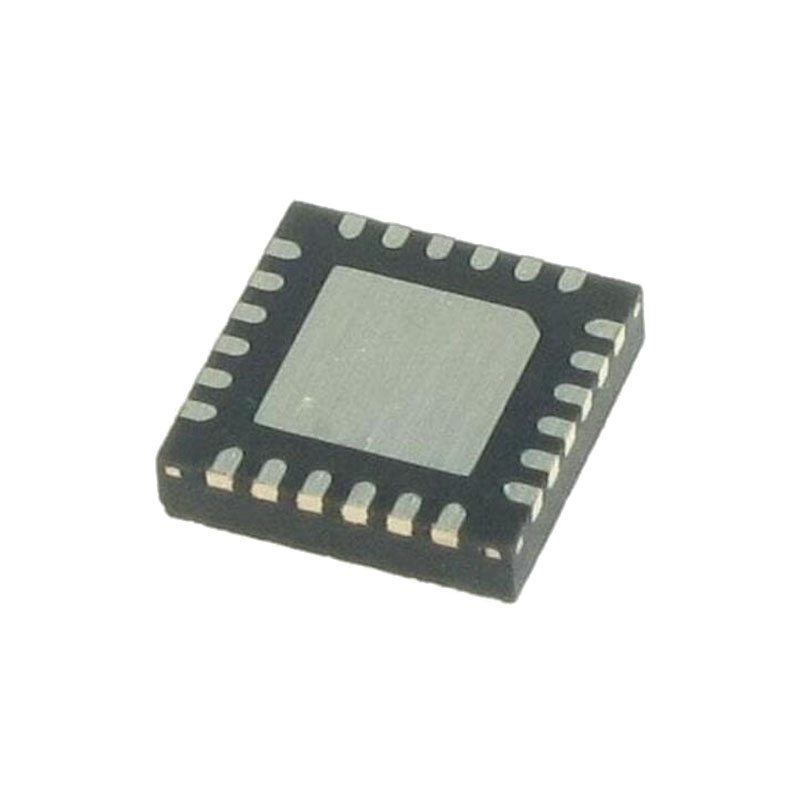
The device includes on-board 3.3V and 5V linear regulators for low-noise analog/logic supply rails. The MAX14827A is available in a (4mm x 4mm) 24-pin TQFN package and a (2.5mm x 2.5mm) 25-pin waferlevel package (WLP) and is specified over the extended -40°C to +125°C temperature range.
Aplicaciones
Industrial sensors
IO-Link sensors and actuators
Safety applications
Ventajas y características
Low Power Dissipation for Small Sensors
2.3Ω/2.7Ω (typ) Driver On-Resistance
70mW (typ) Power Dissipation at 100mA (When Both C/Q and DO Drivers Are Driving)
High Configurability and Integration Reduce SKUs
Auxiliary 24V Digital Output and Input
Selectable Driver Current: 50mA to 250mA
SPI/Pin-Control Interface for Configuration and Monitoring
Multiplexed SPI/UART Interface Option
5V and 3.3V Linear Regulators
Optional External Transistor Supports Higher Regulator Load Capability
Integrated LED Driver
Selectable Driver Integrated Protection Enables Robust Communication
65V Absolute Maximum Ratings on Interface and Supply Pins Allows for Flexible TVS Protection
9V to 60V Specified Operation
Glitch Filters for Improved Burst Resilience and Noise
Thermal Shutdown Auto-Retry Cycling
Hot-Plug Supply Protection
Reverse Polarity Protection of All Sensor Interface Inputs/Outputs
-40°C to +125°C Operating Temperature Range
Descripción detallada
The MAX14827A is an industrial sensor output driver/IO-Link device transceiver. The IC integrates the high voltage functions commonly found in sensors, including two 24V line driver and two on-board linear regulators (LDOs). The MAX14827A can be configured and monitored either through the SPI interface or by setting logic interface pins.
The MAX14827A features multiple programmable functions that allow the user to optimize operation and power dissipation for various loads and application scenarios.The integrated 3.3V and 5V LDOs provide the power needed for low noise analog and logic supply rails.
Apagado térmico
The C/Q and DO drivers, and the V5 and V33 regulators are automatically switched off when the junction temperature exceeds the +165°C (typ) thermal shutdown threshold. SPI communication and and the internal regulators are not disabled during thermal shutdown. In SPI mode, the ThShut bit in the STATUS register and the ThShutInt in the INTERRUPT register are set.
Regulators are automatically switched on when the internal die temperature falls below the thermal shutdown threshold plus hysteresis. If the internal V5 regulator is used, the internal registers return to their default state when the V5 regulator is switched back on.
SPI Burst Access
Burst access allows writing or reading in one block, by only defining the initial register address in the SPI command byte. Once the initial SPI address is received, the MAX14827A automatically increments the register after each SPI data byte. Efficient programming of multiple consecutive registers is thus possible. Chip select, CS/PP, must be kept low during the whole write/read cycle.
The SPI clock continues clocking throughout the burst access cycle. The burst cycle ends when the SPI master pulls CS/PP high.
Microcontroller Interfacing
The logic levels of the microcontroller interface I/Os are defined by VL. Apply a voltage from 2.5V to 5.5V to VL for normal operation. Logic outputs are supplied by VL.
The device can be configured for simultaneous or multiplexed UART communication. When configured for a multipexed UART interface, the SPI interface and UART interface pins are shared.


