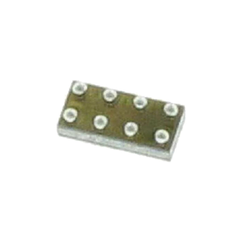
DESCRIPTION GÉNÉRALE
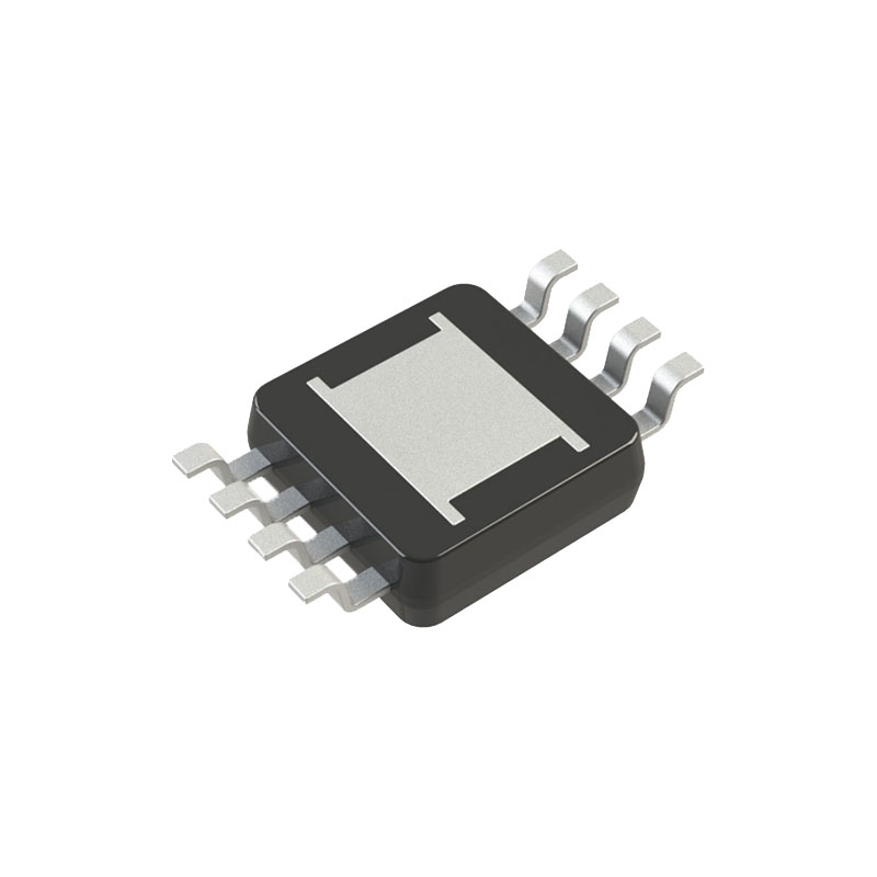
The AD5421 is a complete, loop-powered, 4 mA to 20 mA digital-to-analog converter (DAC) designed to meet the needs of smart transmitter manufacturers in the industrial control industry. The DAC provides a high precision, fully integrated, low cost solution in compact TSSOP and LFCSP packages.
The AD5421 includes a regulated voltage output that is used to power itself and other devices in the transmitter. This regulator provides a regulated 1.8 V to 12 V output voltage. The AD5421 also contains 1.22 V and 2.5 V references, thus eliminating the need for a discrete regulator and voltage reference.
The AD5421 can be used with standard Highway Addressable Remote Transducer (HART®) FSK protocol communication circuitry without any degradation in specified performance. The high speed serial interface is capable of operating at 30 MHz and allows for simple connection to commonly used microprocessors and microcontrollers via a SPI-compatible, 3-wire interface.
The AD5421 is guaranteed monotonic to 16 bits. It provides 0.0015% integral nonlinearity, 0.0012% offset error, and 0.0006% gain error under typical conditions.
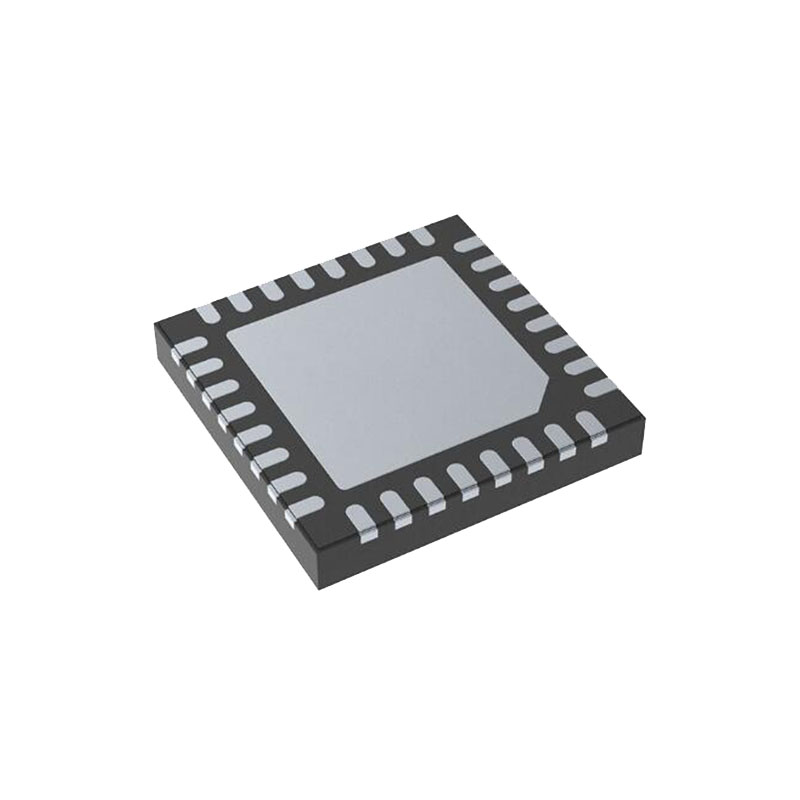
The AD5421 is available in a 28-lead TSSOP and a 32-lead LFCSP specified over the extended industrial temperature range of −40°C to +105°C.
CARACTÉRISTIQUES
16-bit resolution and monotonicity
Pin selectable NAMUR-compliant ranges
4 mA to 20 mA
3.8 mA to 21 mA
3.2 mA to 24 mA
NAMUR-compliant alarm currents
Downscale alarm current = 3.2 mA
Upscale alarm current = 22.8 mA/24 mA
Total unadjusted error (TUE): 0.05% maximum
INL error: 0.0035% FSR maximum
Output TC: 3 ppm/°C typical
Quiescent current: 300 μA maximum
Flexible SPI-compatible serial digital interface with Schmitt triggered inputs
On-chip fault alerts via FAULT pin or alarm current
Automatic readback of fault register on each write cycle
Slew rate control function Gain and offset adjust registers
On-chip reference TC: 4 ppm/°C maximum
Selectable regulated voltage output
Loop voltage range: 5.5 V to 52 V
Temperature range: −40°C to +105°C
TSSOP and LFCSP packages
CANDIDATURES
Industrial process control
4 mA to 20 mA loop-powered transmitters
Smart transmitters
HART network connectivity
THÉORIE DU FONCTIONNEMENT
The AD5421 is an integrated device designed for use in looppowered, 4 mA to 20 mA smart transmitter applications. In a single chip, the AD5421 provides a 16-bit DAC and current amplifier for digital control of the loop current, a voltage regulator to power the entire transmitter, a voltage reference, fault alert functions, a flexible SPI-compatible serial interface, gain and offset adjust registers, as well as other features and functions.
FAULT ALERTS
The AD5421 provides a number of fault alert features. All faults are signaled to the controller via the FAULT pin and the fault register. In the case of a loss of communication between the AD5421 and the microcontroller (SPI fault), the AD5421 programs the loop current to an alarm value. If the controller detects that the FAULT pin is set high, it should then read the fault register to determine the cause of the fault. Note that the watchdog timer does not reset and restart its condition with an alarm active. If the auto fault readback is disabled and an SPI fault occurs, such that the watchdog timer is timed out, the watchdog timer remains inactive until the status register is manually read back by the user. Following this readback, the watchdog timer resumes operation.
Overtemperature Fault
There are two overtemperature alert bits in the fault register: Temp 100°C and Temp 140°C. If the die temperature of the AD5421 exceeds either 100°C or 140°C, the appropriate bit is set. If the Temp 140°C bit is set in the fault register, the FAULT pin is set to logic high.
POWER-ON DEFAULT
The AD5421 powers on with all registers loaded with their default values and with the loop current in the alarm state set to 3.2 mA or 22.8 mA/24 mA (depending on the state of the ALARM_ CURRENT_DIRECTION pin and the selected range). The AD5421 remains in this state until it is programmed with new values. The SPI watchdog timer is enabled by default with a timeout period of 1 sec. If there is no communication with the AD5421 within 1 sec of power-on, the FAULT pin is set.

