Description
The LTC5548 is a high performance, microwave double balanced passive mixer that can be used for frequency upconversion or downconversion. The device is similar to the LTC5549, but with a broadband, differential DC to 6GHz IF port. The LTC5548 is recommended for applications where the IF frequency range extends below 500MHz. For applications where the IF frequency is always above 500MHz, the LTC5549 is recommended, since it includes an integrated IF balun. The LTC5548’s mixer and integrated RF balun are optimized to cover the 2GHz to 14GHz RF frequency range. The device includes an integrated LO amplifier optimized for the 1GHz to 12GHz frequency range, requiring only 0dBm drive. The device also includes an integrated LO frequency doubler, which can be enabled or disabled with a CMOS-compatible control pin. The LTC5548 delivers exceptionally high IIP3 and P1dB, in addition to very low LO to RF and LO to IF leakages. The part also offers high integration in a small package.
Caractéristiques
Upconversion or Downconversion
High IIP3: +24.4dBm at 5.8GHz +21.4dBm at 9GHz
7.1dB Conversion Loss at 5.8GHz
+15.2dBm Input P1dB at 5.8GHz
Integrated LO Buffer: 0dBm LO Drive
Selectable Integrated LO Frequency Doubler
Low LO-RF Leakage: <–30dBm
50Ω Wideband Matched RF and LO Ports
3.3V/120mA Supply
Fast Turn ON/OFF for TDD Operation
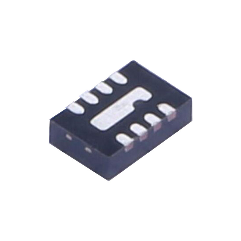
3mm × 2mm, 12-Lead QFN Package
Applications
Microwave Transceivers
Wireless Backhaul
Point-to-Point Microwave
Phased-Array Antennas
C, X and Ku Band RADAR
Test Equipment
Satellite MODEMs
Informations sur les applications
Introduction
The LTC5548 consists of a high linearity double-balanced mixer core, LO buffer amplifier, LO frequency doubler and bias/enable circuits. See the Block Diagram section for a description of each pin function. The RF and LO are singleended terminals. The IF is differential. An external balun is needed if a single-ended IF signal is desired. The LTC5548 can be used as a frequency downconverter where the RF is used as an input and IF is used as an output. It can also be used as a frequency upconverter where the IF is used as an input and RF is used as an output. Low side or high side LO injection can be used.
RF Port
The mixer’s RF port, is connected to the primary winding of an integrated transformer. The primary side of the RF transformer is DC-grounded internally and the DC resistance of the primary side is approximately 3.2Ω. A DC blocking capacitor is needed if the RF source has DC voltage present. The secondary winding of the RF transformer is internally connected to the mixer core. The RF port is broadband matched to 50Ω from 2GHz to 14GHz with a 0.15pF shunt capacitor (C1) located 1.4mm away from the RF pin. The RF port is 50Ω matched from 2GHz to 10GHz without C1. An LO between –6dBm and 6dBm is required for good RF impedance matching. The reference plane for this data is Pin 5 of the IC, with no external matching, and the LO is driven at 7.5GHz.
LO Input
The mixer’s LO input, consists of a single-ended to differential conversion, high speed limiting differential amplifier and an LO frequency doubler. The LO amplifier is optimized for the 1GHz to 12GHz LO frequency range. LO frequencies above or below this frequency range may be used with degraded performance. The LO frequency doubler is controlled by a digital voltage input at X2 (Pin 8). When the X2 voltage is higher than 1.2V, the LO frequency doubler is enabled. When X2 is left open or its voltage is lower than 0.3V, the LO frequency doubler is disabled. The DC voltage at the LO input is about 1.6V. A DC blocking capacitor (C4) is required.