DESCRIPTION
The LTC®6228/LTC6229 are single/dual very fast, low noise rail-to-rail output, unity gain stable op amps. They have a gain-bandwidth product of 890MHz and a slew rate of 500V/μs. The low input referred voltage noise of only 0.88nV/√Hz and low distortion performance of better than
−100dB at 4VP-P even for signals as fast as 2MHz make them ideal for applications that require high dynamic range and deal with high slew rate signals, such as driving A/D converters. Additional features include Shutdown and the ability to enable/disable internal bias current cancel
lation to optimize noise performance.
The combination of low offset, low offset drift, high gain and high CMRR make the LTC6228 family the superior choice for wide dynamic range applications.
The LTC6228 family maintains excellent performance for supply voltages of 2.8V to 11.75V and the devices are specified at supplies of 3V, 5V and 10V(±5V). With an input range extending to the negative rail and an out
put range that encompasses the entire supply range, the operational amplifier can accommodate wide swinging signals, and single supply operation.
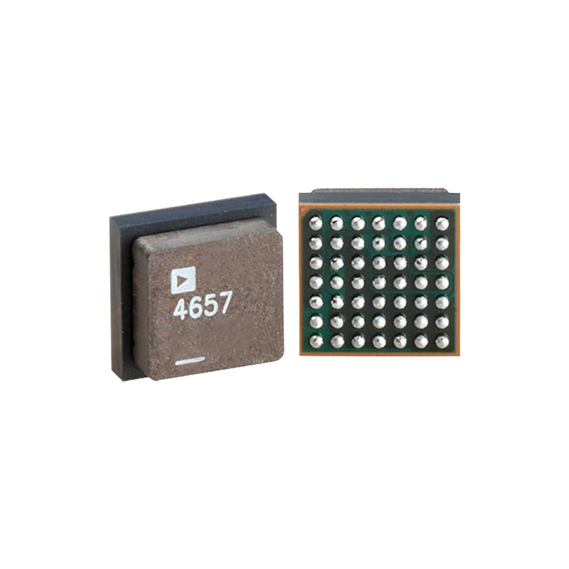
For space constrained PCB layouts, the LTC6228 is available in a 2mm × 2mm DFN and the LTC6229 is available in a 3mm × 3mm DFN. The amplifiers are also available in conventional leaded packages. These amplifiers can be used as improved replacements for many high speed op amps to improve speed, noise, distortion and dynamic range.
CARACTÉRISTIQUES
Ultra Low Voltage Noise: 0.88nV/√Hz
Low Distortion at High Speeds: HD2/HD3 < −100dBc (Av = +1, 4VP-P, 2MHz, RL = 1kΩ)
High Slew Rate: 500V/μs
GBW = 890MHz
–3dB Frequency (AV = +1): 730MHz
Input Offset Voltage: 250μV Max Across Temperature
Offset Drift :0.4μV/°C
Input Common Mode Range Includes Negative Rail
Sortie Swings Rail-to-Rail
Supply Current: 16mA/Channel Typ
Shutdown Supply Current = 500µA
Operating Supply Range: 2.8V to 11.75V
Large Output Current: 80mA Min
Very High Open Loop Gain: 5.6V/μV (135dB), RL = 1kΩ
Operating Temp Range: –40°C to 125°C
Singles in 8-Lead SOIC, TSOT-23, DC-6, Duals in DD10, MS8
CANDIDATURES
Optical Electronics: Fast Transimpedance Amplifiers
Driving High Dynamic Range A/D Converters
Filtres actifs
Video Amplifiers
High Speed Differential to Single-Ended Conversion
Low Voltage Hi-Fi Amplification
INFORMATIONS SUR LES APPLICATIONS
Description du circuit
The LTC6228/LTC6229 have an input signal range that extends from the negative power supply to 1.2V below the positive power supply. Figure 1 depicts a simplified schematic of the amplifier. The input stage consists of PNP transistors Q1 and Q2. At the input stage, devices
Q18 and Q19 act to cancel the bias current of the input pair when bias cancellation is enabled. Bootstrap transistor Q13 and R5 match the collector and emitter voltages of Q11 and Q12, thus enhancing gain by improving output impedance. By making the collector current of Q13 twice
that of Q11 and Q12, the base currents of Q11 and Q12 do not contribute towards mismatch between the collector currents of Q9 and Q8. This improves DC accuracy. A pair of complementary common emitter stages, Q15 and Q14, enables the output to swing to either rail. The SHDN
Interface block translates the SHDN signal into 2 signals, pwr_dn for powering down the device (by deactivating current sources I1 – I4) and putting the output in a high impedance state (by shorting the bases of Q15/Q14 to the SHDN supplies via M2 and M1), and disable_bias, which disables the input bias cancellation circuit, by shorting the base of
Q19 to V– through M3.
Input Bias Current
The LTC6228 family has an input bias current of approximately 16μA. For the LTC6228 and the LTC6229DD10, the input bias current can be reduced to under 2.5μA at room temperature when the SHDN pin voltage is taken to within 350mV of the positive power supply. This capability enables the input bias current cancellation circuitry, allowing the amplifiers to be used in DC applications involving source impedances.
When input bias current cancellation is enabled and the input common mode voltage is within approximately 500mV of V–, the bias cancellation is no longer effective, because transistors Q18 and Q19 in Figure 1 enter
saturation. The input bias current can then exceed 50μA or higher, which is more than the input bias current without input bias cancellation. Additionally when input bias current cancellation is enabled, the current noise increases. The decision to use input bias cancellation
should be made with the end application’s specifications and conditions in mind.
If the SHDN pin is left floating, input bias cancellation is
not enabled, which may be suitable for many applications.