CARACTÉRISTIQUES
Deux amplificateurs hacheurs intégrés à dérive nulle, rail à rail
2,7V à 5,5V Plage de tension d'entrée
1.5A Capacité de conduite
1% Précision 2,5V Sortie de référence interne
Surveillance de la tension et du courant du TEC
Limite de courant de chauffage et de refroidissement programmable indépendante
Tension maximale programmable du TEC
Défaut 2MHz Fréquence de commutation
Synchronisation de 1,85MHz à 3,25MHz
Capable d'utiliser des capteurs thermiques NTC, PTC et RTD
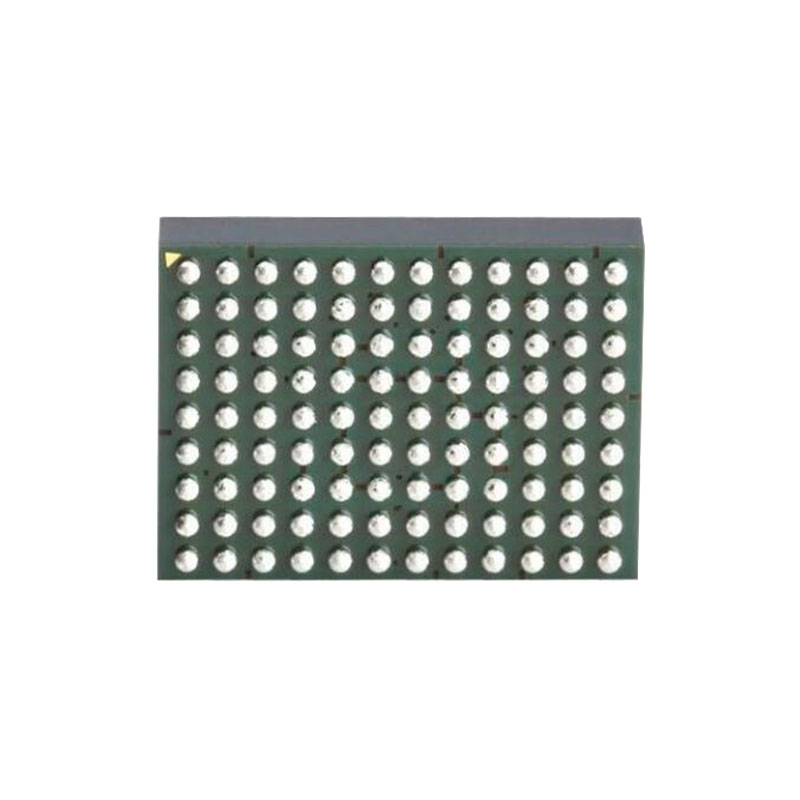
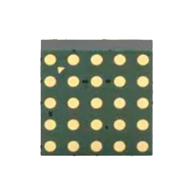
3,5 mm × 4 mm × 1,3 mm Boîtier LGA
CANDIDATURES
TEC Contrôle de la température
Système de réseau optique, module optique
Système LiDAR
DESCRIPTION
Le LTM4663 est un régulateur de refroidisseur thermoélectrique (TEC) µModule® complet de 1,5A dans un petit boîtier LGA de 3,5mm × 4mm × 1,3mm. Le boîtier comprend le contrôleur TEC, l'étage de puissance linéaire, le régulateur à découpage, l'inductance et tous les composants de support.
Fonctionnant sur une gamme de tension d'entrée de 2,7V à 5,5V, le LTM4663 supporte un courant continu de 1,5A en entrée ou en sortie. Seuls les condensateurs d'entrée et de sortie sont nécessaires. Le LTM4663 possède deux amplificateurs, à dérive nulle, à découpage rail à rail, pour servir d'amplificateur d'entrée de thermistance et de boucle de contrôle de retour de température.
Le LTM4663 supporte les thermistances NTC, PTC et les détecteurs de température résistive (RTD). Les courants maximums de refroidissement et de chauffage peuvent être programmés indépendamment, ainsi que la tension maximum du TEC.
Le LTM4663 est disponible en finition LGA conforme à la norme RoHS.
FONCTIONNEMENT
Le LTM4663 est un régulateur complet de µmodule de refroidisseur thermoélectrique (TEC) qui règle, stabilise et surveille la température du TEC. Il peut délivrer jusqu'à 1,5A de courant d'entrée ou de sortie avec des condensateurs externes d'entrée et de sortie. Fonctionnant sur une gamme de tension d'entrée de 2.7V à 5.5V, le LTM4663 contrôle un pont en H à FET interne par lequel la direction du courant alimenté à travers le TEC peut être soit positive (pour le mode refroidissement), soit négative (pour le mode chauffage).
Le LTM4663 possède deux amplificateurs autocorrectifs, à mise à zéro automatique (Chopper 1 et Chopper 2) pour linéariser l'entrée du capteur thermique et pour former une boucle analogique de contrôle de la température. Avec les amplificateurs de chopper à dérive nulle, une très bonne stabilité de température à long terme est maintenue grâce à une boucle de contrôle de température autonome. Voir la figure 18 pour un aperçu de la configuration de la commande PID analogique, et la figure 19 pour la configuration de la commande PID numérique.
Le LTM4663 peut également être configuré pour être utilisé dans une boucle PID contrôlée par logiciel. Dans ce scénario, l'amplificateur Chopper 1 peut être configuré comme un amplificateur d'entrée de thermistance connecté à un convertisseur log-numérique (ADC) externe de mesure de température. L'amplificateur Chopper 2 est utilisé comme tampon pour le convertisseur numérique-analogique externe (DAC), qui contrôle le point de consigne de la température. Connecter le CNA à TSET et court-circuiter les broches PAMPN et PAMPOUT. Voir la figure 19 pour une vue d'ensemble de la façon de configurer le circuit externe du LTM4463 pour la commande numérique PID.
Pour fournir une bonne efficacité et une solution de petite taille, le LTM4663 utilise une alimentation à mode de commutation PWM d'un côté du pont en H et un étage de puissance linéaire de l'autre côté. Une fréquence de commutation par défaut de 2MHz et un condensateur de 10µF maintiennent moins de 1% de l'ondulation de tension de sortie la plus défavorable à travers le TEC.
La tension maximale aux bornes du TEC et le courant traversant le TEC sont réglés à l'aide des broches VLIM/SD et ILIM. Les courants maximaux de refroidissement et de chauffage peuvent être réglés indépendamment pour permettre des limites asymétriques de refroidissement et de chauffage. La tension et le courant du TEC en temps réel peuvent être contrôlés à l'aide des broches VTEC et ITEC.
THÉORIE DU FONCTIONNEMENT
Le LTM4663 possède deux étages de puissance de type demi-pont, un régulateur à mode de commutation PWM et un étage de puissance linéaire, pour permettre au courant d'entrer ou de sortir du dispositif TEC connecté entre les deux.
La température de l'objet est mesurée par un capteur thermique externe. La température détectée (tension) est renvoyée au LTM4663 par la broche TFB pour compléter une boucle de contrôle thermique fermée. L'amplificateur d'entrée de la thermistance gagne la tension détectée par la thermistance, puis la transmet à l'amplificateur de compensation PID. L'amplificateur de compensation PID compense alors une réponse de la boucle de rétroaction pour piloter à la fois le régulateur à mode de commutation PWM et l'étage de puissance linéaire afin de piloter le TEC pour chauffer ou refroidir l'objet.