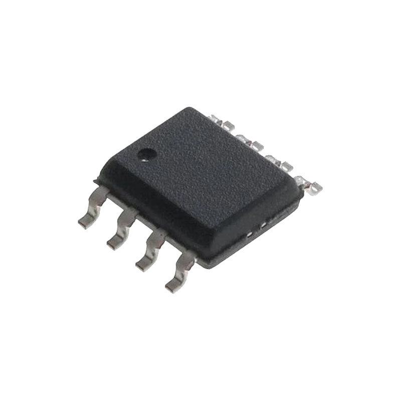
Description générale
The MAX6816/MAX6817/MAX6818 are single, dual, and octal switch debouncers that provide clean interfacing of mechanical switches to digital systems. They accept one or more bouncing inputs from a mechanical switch and produce a clean digital output after a short, preset qualification delay. Both the switch opening bounce and the switch closing bounce are removed. Robust switch inputs handle ±25V levels and are ±15kV ESD-protected for use in harsh industrial environments. They feature single-supply operation from +2.7V to +5.5V. Undervoltage-lockout circuitry ensures the output is in the correct state upon power-up.The MAX6818 octal switch debouncer is designed for data-bus interfacing. The MAX6818 monitors switches and provides a switch change-of-state output (CH), simplifying microprocessor (µP) polling and interrupts. Additionally, the MAX6818 has three-state outputs controlled by an enable (EN) pin, and is pin-compatible with the LS573 octal latch (except for the CH pin), allowing easy interfacing to a digital data bus.
Avantages et caractéristiques
Switch Debouncer Integration Simplifies System
Interface to Mechanical Switches
Single-Supply Operation from +2.7V to +5.5V
No External Components Required
Single (MAX6816), Dual (MAX6817), and Octal (MAX6818) Versions Available
6μA Supply Current
Built-In Protection Circuitry Improves System
Reliability
Inputs Can Exceed Power Supplies up to ±25V
ESD Protection for Input Pins
±15kV—Human Body Model
±8kV—IEC 1000-4-2, Contact Discharge
±15kV—IEC 1000-4-2, Air-Gap Discharge
Octal Version Provides Direct Data
Bus Interface
Three-State Outputs for Directly Interfacing to μP
Switch Change-of-State Output Simplifies Polling and Interrupts
Pin-Compatible with ‘LS573
Theory of Operation
The MAX6816/MAX6817/MAX6818 are designed to eliminate the extraneous level changes that result from interfacing with mechanical switches (switch bounce). Virtually all mechanical switches bounce upon opening or closing. These switch debouncers remove bounce when a switch opens or closes by requiring that sequentially clocked inputs remain in the same state for a number of sampling periods. The output does not change until the input is stable for a duration of 40ms.The circuit block diagram shows the functional blocks consisting of an on-chip oscillator, counter, exclusive-NOR gate, and D flip-flop. When the input does not equal the output, the XNOR gate issues a counter reset. When the switch input state is stable for the full qualification period, the counter clocks the flip-flop, updating the output. Shows the typical opening and closing switch debounce operation. On the MAX6818, the change output (CH) is updated simultaneously with the switch outputs.
Undervoltage Lockout
The undervoltage-lockout circuitry ensures that the out-puts are at the correct state on power-up. While the supply voltage is below the undervoltage threshold (typically 1.9V), the debounce circuitry remains transparent. Switch states are present at the logic outputs with no debouce delay.
Robust Switch Inputs
The switch inputs on the MAX6816–MAX6818 have overvoltage-clamping diodes to protect against damaging fault conditions. Switch input voltage scan safely swing ±25V to ground .Proprietary ESD-protection structures protect against high ESD encountered in harsh industrial environments, membrane keypads, and portable applications. They are designed to withstand ±15kV per the IEC 1000-4-2 Air-Gap Discharge Test and ±8kV per the IEC 1000-4-2 Contact Discharge Test.Since there are 63kΩ (typical) pullup resistors connected to each input, driving an input to -25V draws approximately 0.5mA (up to 4mA for eight inputs) from the VCC supply. Driving an input to +25V will cause approximately 0.32mA of current (up to 2.6mA for eight inputs) to flow back into the VCC supply. If the total system VCC supply current is less than the current flowing back into the VCC supply, VCC will rise above normal levels.In some low-current systems, a zener diode on VCC may be required.As with all Maxim devices, ESD-protection structures are incorporated on all pins to protect against electrostatic discharges encountered during handling and assembly.

