DESCRIPTION
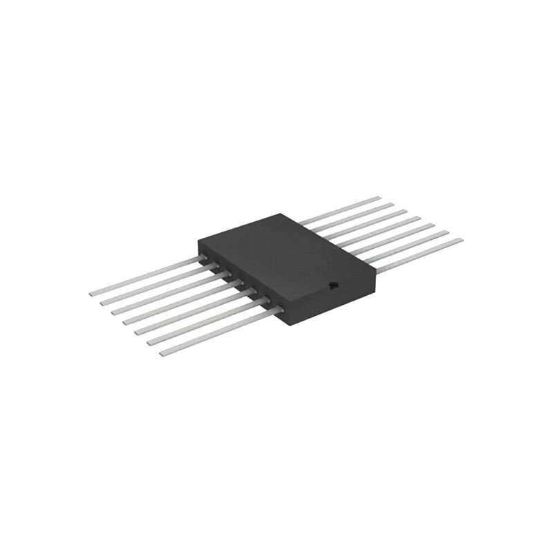
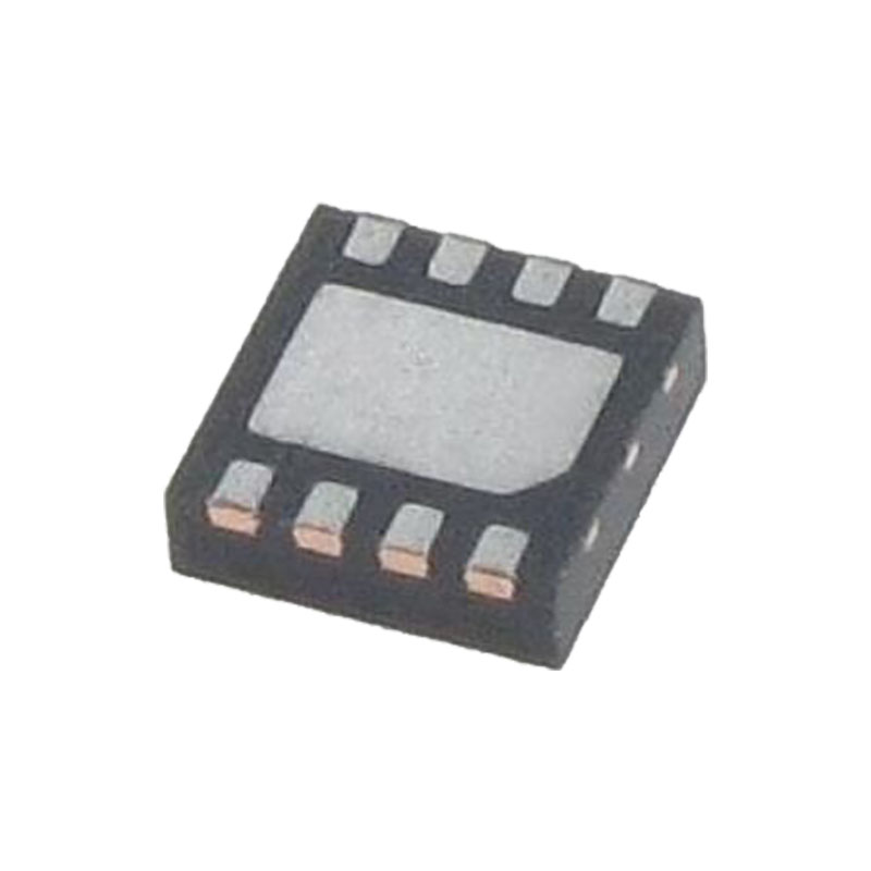
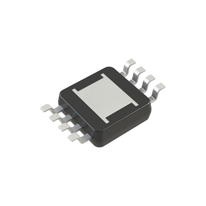
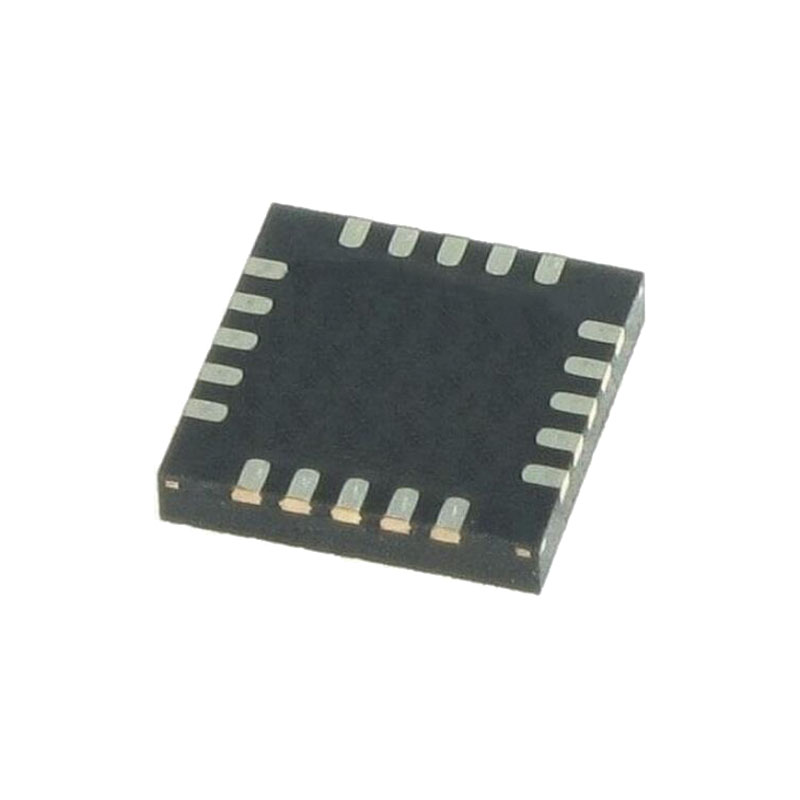
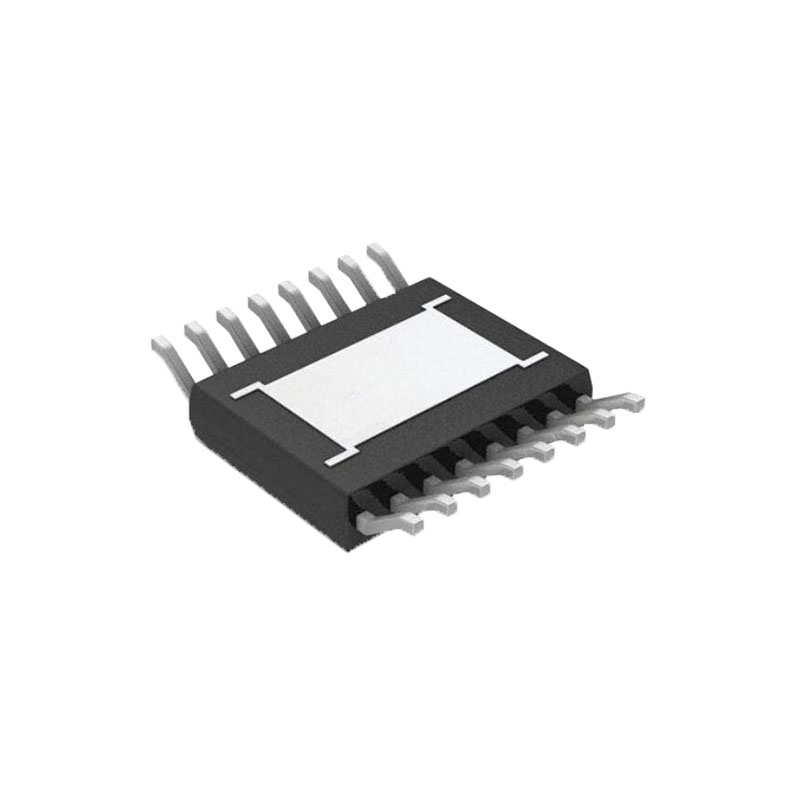
Les options de boîtiers comprennent des boîtiers en plastique "Small Outline", des supports de puce en céramique et des boîtiers plats, ainsi que des DIP en plastique et en céramique.
PAQUET SN54LS54 : J OU W
Ces dispositifs contiennent des portes AND-OR-INVERT de 4 largeurs.
Ils remplissent les fonctions booléennes suivantes :
SN54 Y=AB+CD+EF+GH
SNLS54 Y = AB + CED + FGH + IJ
Les SN5454 et SN54LS54 sont caractérisés pour un fonctionnement sur toute la plage de température militaire de -55℃ à 125℃.
Les SN7454 et SN74LS54 sont caractérisés pour un fonctionnement à partir de 0℃ à 70℃.
Valeurs nominales maximales absolues sur la plage de température de fonctionnement à l'air libre (sauf indication contraire)
Tension d'alimentation, VCC, I voir Note 1) : 7V
Tension d'entrée : 7V
Température de fonctionnement à l'air libre :
SN54LS54 : -55℃ à 125℃/SN74LS54 : 0℃ à 70℃
Plage de température de stockage : -65℃ à 150℃
NOTE 1 : Les valeurs de tension se rapportent à la borne de terre du réseau.
Conditions d'utilisation recommandées
| SN54LS54 | SN74LS54 | UNITÉ | |||||
| MIN | NOM | MAX | MIN | NOM | MAX | ||
| VCc Tension d'alimentation | 4.5 | 5 | 5.5 | 4.75 | 5 | 5.25 | V |
| VIH Tension d'entrée de haut niveau | 2 | 2 | V | ||||
| VIL Tension d'entrée basse | 0.7 | 0.8 | V | ||||
| IOH Courant de sortie de haut niveau | -0.4 | -0.4 | mA | ||||
| IOL Courant de sortie de bas niveau | 4 | 8 | mA | ||||
| TA Température de fonctionnement à l'air libre | -55 | 125 | 0 | 70 | ℃ | ||
Caractéristiques électriques sur la plage de température à l'air libre recommandée (sauf indication contraire)
| PARAMÈTRE | CONDITIONS D'ESSAI↑ | SN54LS54 | SN74LS54 | UNITÉ | ||||
| MIN | TYP* | MAX | MIN | TYP* | MAX | |||
| VIK | Vcc=MIN, VIH=-18mA | -1.5 | -1.5 | V | ||||
| VOH | Vcc=MIN, VIL=MAX, IOH=-0,4mA | 2.5 | 3.4 | 2.5 | 3.4 | V | ||
| VOL | Vcc=MIN, VIH=2V, IOL=4mA | 0.25 | 4 | 0.25 | 4 | V | ||
| Vcc=MIN, VIH=2V, IOL=8mA | 0.35 | 0.5 | mA | |||||
| II | Vcc=MAX, VI=7V | 0.1 | 0.1 | μA | ||||
| IIH | Vcc=MAX, VI=2,7V | 20 | 20 | mA | ||||
| IIL | Vcc=MAX, VI=0,4V | -0.4 | -0.4 | mA | ||||
| IOS | Vcc=MAX | -20 | -100 | -20 | -100 | mA | ||
| ICCH | Vcc=MAX, VI=0V | 0.8 | 1.6 | 0.8 | 1.6 | mA | ||
| ICCL | Vcc=MAX, voir note 2 | 1 | 2 | 1 | 2 | mA | ||
↑Pour les conditions indiquées comme MIN ou MAX, utiliser la valeur appropriée spécifiée dans les conditions de fonctionnement recommandées.
* Toutes les valeurs typiques sont à VCC = 5 V, TA = 25 °C.
§Il ne faut pas court-circuiter plus d'une sortie à la fois et la durée du court-circuit ne doit pas dépasser une seconde.
NOTE 2 : Toutes les entrées d'une porte ET à 4,5 V, toutes les autres à GND.
Caractéristiques de commutation,VCC = 5 V,TA = 25°C (voir note 3)
| PARAMÈTRE | FORMULAIRE (ENTRÉE) |
POUR (SORTIE) |
CONDITIONS D'ESSAI | MIN | TYP | MAX | UNITÉ |
| tPLH | Tous | Y | RL = 2KΩ CL = 15pF | 12 | 20 | ns | |
| tPHL | 12.5 | 20 | ns |
NOTE 3 : Les circuits de charge et les formes d'onde de tension sont indiqués à la section 1.
AUTRES
RoHS : TI définit "RoHS" comme des produits semi-conducteurs conformes aux exigences RoHS actuelles de l'UE pour les 10 substances RoHS, y compris l'exigence que les substances RoHS ne dépassent pas 0,1% en poids dans les matériaux homogènes. Lorsqu'ils sont conçus pour être soudés à des températures élevées, les produits "RoHS" peuvent être utilisés dans des procédés sans plomb spécifiques. TI peut faire référence à ces types de produits en les appelant "sans plomb".
Exempt de RoHS : TI définit l'expression "exempt de RoHS" comme désignant les produits qui contiennent du plomb mais qui sont conformes à la directive RoHS de l'UE en vertu d'une exemption spécifique de RoHS de l'UE.
Vert : TI définit le terme "vert" comme la teneur en retardateurs de flamme à base de chlore (Cl) et de brome (Br) qui répondent aux exigences de la norme JS709B en matière de faible teneur en halogènes, avec un seuil <=1000 ppm. Les retardateurs de flamme à base de trioxyde d'antimoine doivent également répondre à l'exigence d'un seuil <=1000 ppm.
MSL, température de pointe - Le niveau de sensibilité à l'humidité selon les classifications de la norme industrielle JEDEC et la température de pointe de la soudure.
Il peut y avoir un marquage supplémentaire concernant le logo, le code de traçabilité du lot ou la catégorie environnementale sur l'appareil.
Les marquages de dispositifs multiples seront placés entre parenthèses. Un seul marquage, contenu entre parenthèses et séparé par un "~", apparaîtra sur un dispositif. Si une ligne est en retrait, elle est la suite de la ligne précédente et les deux combinées représentent l'ensemble du marquage de l'appareil.
Finition du plomb/Matériau de la bille - Les dispositifs pouvant être commandés peuvent avoir plusieurs options de finition du matériau. Les options de finition sont séparées par un trait vertical. Les valeurs de finition du plomb/matériau de la bille peuvent s'étendre sur deux lignes si la valeur de la finition dépasse la largeur maximale de la colonne.

