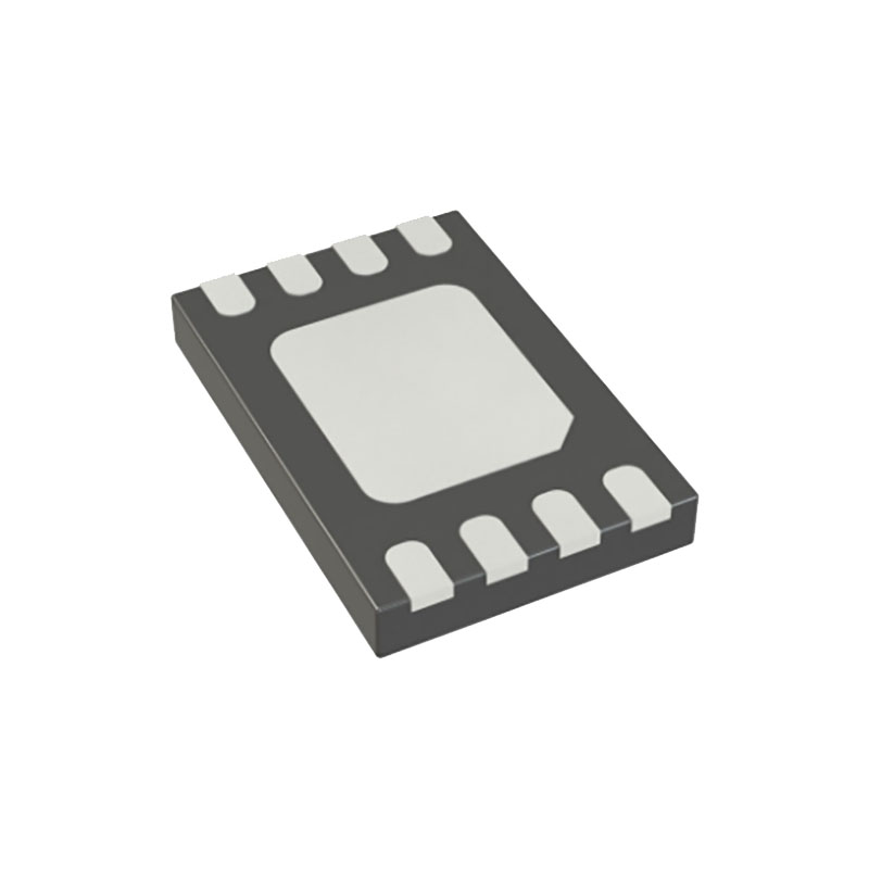
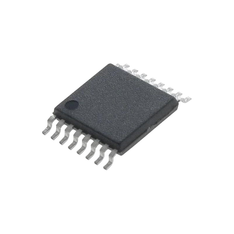
概要
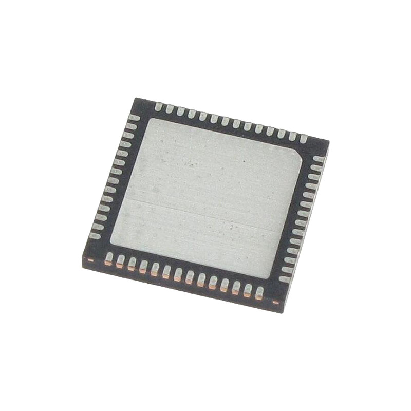
The MAX96724/F/R deserializer converts four GMSL™2/1 inputs to 1, 2, or 4 MIPI D-PHY or C-PHY outputs. The device allows simultaneous transmit bidirectional transmissions over 50Ω coax or 100Ω STP cables that meet the GMSL channel specification. Contact the factory for the GMSL supporting collateral.
Up to four remotely located sensors can be supported using industry-standard coax or STP interconnects. Each GMSL2 serial link operates at a fixed rate of 3Gbps or 6Gbps in the forward direction and 187.5Mbps in the reverse direction. The MAX96724/F/R supports both aggregation and replication of video data, enabling streams from multiple remotely located sensors to be combined and routed to one or more of the available CSI-2 outputs.
アプリケーション
High-Resolution Camera Systems
Advanced Driver Assistance Systems (ADAS)
Thermal Management
Power consumption of the MAX96724/F/R varies based on the use case. Care must be taken by the user to provide sufficient heat dissipation with proper board design and cooling techniques. The package’s exposed pad must be connected to the PCB ground plane by an array of vias. This approach simultaneously provides the lowest electrical and thermal impedances.
System thermal management must keep the operating junction temperature below +125°C to meet electrical specifications and avoid impacting device reliability.
Control Channel Programming
MAX96724/F/R internal registers can be accessed locally via any of the two available I2C ports. Lower indexed ports have a higher priority in the case of simultaneous queries. By default, remote GMSL serializer register access is available via I2C port 0 only. However, the internal I2C crossover enables any of the two ports to connect to the control channel, which thereby provides access to remote serializer registers. Only one of the two ports can access the control channel at a given time, and the other I2C port then functions essentially as remote pass-throughs from the perspective of the serializer. See I2C for further details regarding the routing of I2C ports in the MAX96724/F/R. For multi-master configurations with microcontrollers connected to both the serializer and deserializer, bus contention can be avoided by using register settings to disable the remote control channel.
Host-to-Peripheral Main I2C and Pass-Through I2C Communication
When communicating between a host and peripheral, main and pass-through I2C operation is the same. An I2C tunnel across the GMSL2 link connects the host’s I2C master to the remote I2C slave. This logically connects separated I2C buses, enabling I2C transactions across the serial link to occur (with some delay) as if performed on the same physical I2C bus. The GMSL2 serializer and deserializer are intermediary devices; the host I2C master connects to a GMSL2 device I2C slave, and the peripheral I2C slave connects to a GMSL2 device I2C master.
For example, when the host I2C master transacts on one side of the link (local-side), the I2C slave of the local-side GMSL2 device forwards data to the other side (remote-side). Data is then received by the I2C master of the remote-side GMSL2 device, which in turn generates the same I2C transaction with the peripheral slave I2C. The remote-side GMSL2 device sends back any I2C data expected by the local-side.
The I2C interface uses clock stretching (holding SCL low) to account for timing differences between master and slave and to allow time for data to be forwarded and received across the serial link. The host I2C master and peripheral I2C slave must support clock stretching by the GMSL2 device.
SDA and SCL lines operate as both an input and an open-drain output. External pullup resistors are required on SDA and SCL.
Each transmission consists of a START condition sent by a master, followed by the device’s 7-bit slave address plus a R/W bit, register address bytes, one or more data bytes, and finally a STOP condition. Register addresses are 16-bits wide. Single or multiple data bytes can be written or read (by address autoincrements).

