FEATURES
AD5280: 1 channel
AD5282: 2 channels
256 positions
+10 V to +15 V single supply; ±5.5 V dual-supply operation
Fixed terminal resistance: 20 kΩ, 50 kΩ, 200 kΩ
Low temperature coefficient: 30 ppm/°C
Power-on midscale preset1
Programmable reset
Operating temperature: −40oC to +85oC
I2C-compatible interface
APPLICATIONS
Multimedia, video, and audio
Communications
Mechanical potentiometer replacement
Instrumentation: gain, offset adjustment
Programmable voltage source
Programmable current source
Line impedance matching
GENERAL DESCRIPTION
The AD5280/AD5282 are single-channel and dual-channel, 256-position, digitally controlled variable resistors (VRs)2. The devices perform the same electronic adjustment function as a potentiometer, trimmer, or variable resistor. Each VR offers a completely programmable value of resistance between the A terminal and the wiper or the B terminal and the wiper. The fixed A-to-B terminal resistance of 20 kΩ, 50 kΩ, or 200 kΩ has a 1% channel-to-channel matching tolerance. The nominal temperature coefficient of both parts is 30 parts per million/ degrees centigrade (ppm/°C). Another key feature is that the parts can operate up to +15 V or ±5 V.
Wiper position programming defaults to midscale at system power-on. When powered, the VR wiper position is programmed by an I2C-compatible, 2-wire serial data interface. The AD5280/ AD5282 feature sleep mode programmability. This allows any level of preset in power-up and is an alternative to a costly EEPROM solution. Both parts have additional programmable logic outputs that enable users to drive digital loads, logic gates, LED drivers, and analog switches in their system.
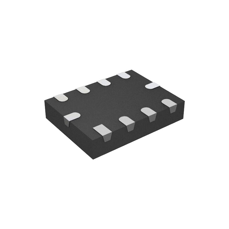
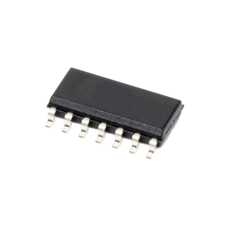
The AD5280/AD5282 are available in thin, surface-mounted 14-lead TSSOP and 16-lead TSSOP. All parts are guaranteed to operate over the extended industrial temperature range of −40°C to +85°C. For 3-wire SPI-compatible interface applications.
THEORY OF OPERATION
The AD5280/AD5282 are single-channel and dual-channel, 256-position, digitally controlled variable resistors (VRs). To program the VR settings, see the Digital Interface section. Both parts have an internal power-on preset that places the wiper at midscale during power-on, which simplifies the fault condition recovery at power-up. Operation of the power-on preset function also depends on the state of the VL pin.
RHEOSTAT OPERATION
The nominal resistance of the RDAC between Terminal A and Terminal B is available in 20 kΩ, 50 kΩ, and 200 kΩ. The final two or three digits of the part number determine the nominal resistance value, for example, 20 kΩ = 20, 50 kΩ = 50, and 200 kΩ = 200. The nominal resistance (RAB) of the VR has 256 contact points accessed by the wiper terminal, plus the B terminal contact. The eight-bit data in the RDAC latch is decoded to select one of the 256 possible settings. Assuming that a 20 kΩ part is used, the wiper’s first connection starts at the B terminal for data 0x00. Because there is a 60 Ω wiper contact resistance, such a connection yields a minimum of 60 Ω resistance between Terminal W and Terminal B.
The nominal resistance of the RDAC between Terminal A and Terminal B is available in 20 kΩ, 50 kΩ, and 200 kΩ. The final two or three digits of the part number determine the nominal resistance value, for example, 20 kΩ = 20, 50 kΩ = 50, and 200 kΩ = 200. The nominal resistance (RAB) of the VR has 256 contact points accessed by the wiper terminal, plus the B terminal contact. The eight-bit data in the RDAC latch is decoded to select one of the 256 possible settings. Assuming that a 20 kΩ part is used, the wiper’s first connection starts at the B terminal for data 0x00. Because there is a 60 Ω wiper contact resistance, such a connection yields a minimum of 60 Ω resistance between Terminal W and Terminal B.
POTENTIOMETER OPERATION
The digital potentiometer easily generates a voltage divider at wiper to B and wiper to A to be proportional to the input voltage at A to B. Unlike the polarity of VDD – VSS, which must be positive, voltage across A to B, W to A, and W to B can be at either polarity, provided that VSS is powered by a negative supply.


