GENERAL DESCRIPTION
The ADM1490E/ADM1491E are RS-485/RS-422 transceivers with ±8 kV ESD protection and are suitable for high speed, full duplex communication on multi point transmission lines. In particular, the ADM1490E/ADM1491E are designed for use in motor control applications requiring communications at data rates up to 16 Mbps.
The ADM1490E/ADM1491E are designed for balanced transmission lines and comply with TIA/EIA-485-A-98. The devices each have a 12 kΩ receiver input impedance for unit load RS-485 operation, allowing up to 32 nodes on the bus.
The differential transmitter outputs and receiver inputs feature electrostatic discharge circuitry that provides protection to ±8 kV using the human body model (HBM).
The ADM1490E/ADM1491E operate from a single 5 V power supply. Excessive power dissipation caused by bus contention or output shorting is prevented by short-circuit protection and thermal circuitry. Short-circuit protection circuits limit the maximum output current to ±250 mA during fault conditions. A thermal shutdown circuit senses if the die temperature rises above 150°C and forces the driver outputs into a high impedance state under this condition.
The receiver of the ADM1490E/ADM1491E contains a fail-safe feature that results in a logic high output state if the inputs are unconnected (floating).
The ADM1490E/ADM1491E feature extremely fast and closely matched switching times. Minimal driver propagation delays permit transmission at data rates up to 16 Mbps, and low skew minimizes EMI interference.
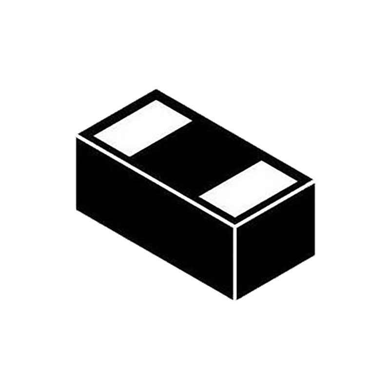
The ADM1490E/ADM1491E are fully specified over the commercial and industrial temperature ranges. The ADM1491E is also available in two packages: a narrow body, 14-lead SOIC and a 10-lead MSOP.
THEORY OF OPERATION
The ADM1490E/ADM1491E are RS-422/RS-485 transceivers that operate from a single 5 V ± 5% power supply. The ADM1490E/ADM1491E are intended for balanced data transmission and comply with both TIA/EIA-485-A and TIA/EIA-422-B. Each device contains a differential line driver and a differential line receiver and is suitable for full-duplex data transmission.
The input impedance of the ADM1490E/ADM1491E is 12 kΩ, allowing up to 32 transceivers on the differential bus. A thermal shutdown circuit prevents excessive power dissipation caused by bus contention or by output shorting. This feature forces the driver output into a high impedance state if, during fault conditions, a significant temperature increase is detected in the internal driver circuitry.
The receiver contains a fail-safe feature that results in a logic high output state if the inputs are unconnected (floating).
The ADM1490E/ADM1491E feature very low propagation delay,ensuring maximum baud rate operation. The balanced driver ensures distortion-free transmission.Another important specification is a measure of the skew between the complementary outputs. Excessive skew impairs the noise immunity of the system and increases the amount of electromagnetic interference (EMI).
ESD TRANSIENT PROTECTION SCHEME
The ADM1490E/ADM1491E use protective clamping structures on their inputs and outputs to clamp the voltage to a safe level and dissipate the energy present in ESD (electrostatic). The protection structure achieves ESD protection up to ±8 kV human body model (HBM).
ESD Testing
Two coupling methods are used for ESD testing: contact discharge and air gap discharge. Contact discharge calls for a direct connection to the unit being tested; air gap discharge uses a higher test voltage but does not make direct contact with the unit under test. With air discharge, the discharge gun is moved toward the unit under test, developing an arc across the air gap; therefore,the term air discharge. This method is influenced by humidity, temperature, barometric pressure, distance, and rate of closure of the discharge gun. The contact discharge method, though less realistic, is more repeatable and is gaining acceptance and preference over the air gap method.
Although very little energy is contained within an ESD pulse, the extremely fast rise time, coupled with high voltages, can cause failures in unprotected semiconductors. Catastrophic destruction can occur immediately because of arcing or heating. Even if catastrophic failure does not occur immediately, the device can suffer from parametric degradation, resulting in degraded performance.The cumulative effects of continuous exposure can eventually lead to complete failure.