GENERAL DESCRIPTION
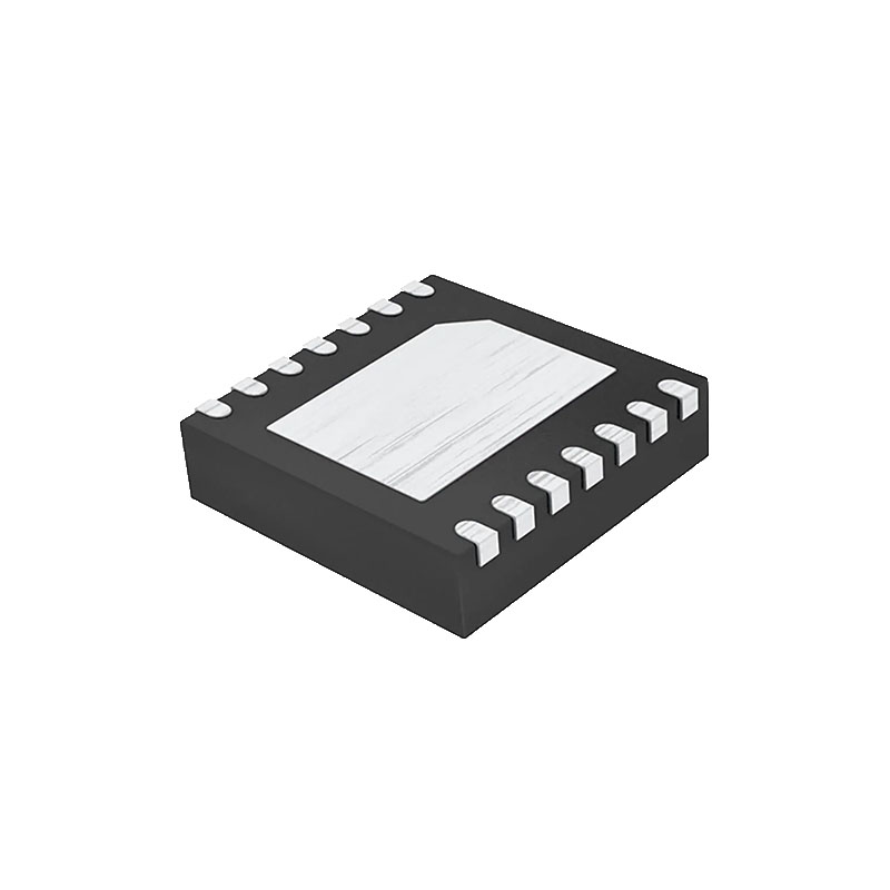
The ADuM1400/ADuM1401/ADuM14021 are quad-channel digital isolators based on Analog Devices, Inc., iCoupler technology. Combining high speed CMOS and monolithic air core transformer technology, these isolation components provide outstanding performance characteristics superior to alternatives, such as optocoupler devices.
By avoiding the use of LEDs and photodiodes, iCoupler devices remove the design difficulties commonly associated with optocouplers. The typical optocoupler concerns regarding uncertain current transfer ratios, nonlinear transfer functions, and temperature and lifetime effects are eliminated with the simple iCoupler digital interfaces and stable performance characteristics.
The need for external drivers and other discrete components is eliminated with these iCoupler products. Furthermore, iCoupler devices consume one tenth to one sixth of the power of optocouplers at comparable signal data rates.
The ADuM1400/ADuM1401/ADuM1402 isolators provide four independent isolation channels in a variety of channel configurations and data rates. All models operate with the supply voltage on either side ranging from 2.7 V to 5.5 V, providing compatibility with lower voltage systems as well as enabling a voltage translation functionality across the isolation barrier. In addition, the ADuM1400/ ADuM1401/ADuM1402 provide low pulse width distortion (<2 ns for CRW grade) and tight channel-to-channel matching (<2 ns for CRW grade). Unlike other optocoupler alternatives, the ADuM1400/ADuM1401/ADuM1402 isolators have a patented refresh feature that ensures dc correctness in the absence of input logic transitions and when power is not applied to one of the supplies.
FEATURES
Qualified for automotive applications
Low power operation
5 V operation
1.0 mA per channel maximum at 0 Mbps to 2 Mbps
3.5 mA per channel maximum at 10 Mbps
31 mA per channel maximum at 90 Mbps
3 V operation
0.7 mA per channel maximum at 0 Mbps to 2 Mbps
2.1 mA per channel maximum at 10 Mbps
20 mA per channel maximum at 90 Mbps
Bidirectional communication
3 V/5 V level translation
High temperature operation: 125°C
High data rate: dc to 90 Mbps (NRZ)
Precise timing characteristics
2 ns maximum pulse width distortion
2 ns maximum channel-to-channel matching
High common-mode transient immunity: >25 kV/μs
Output enable function
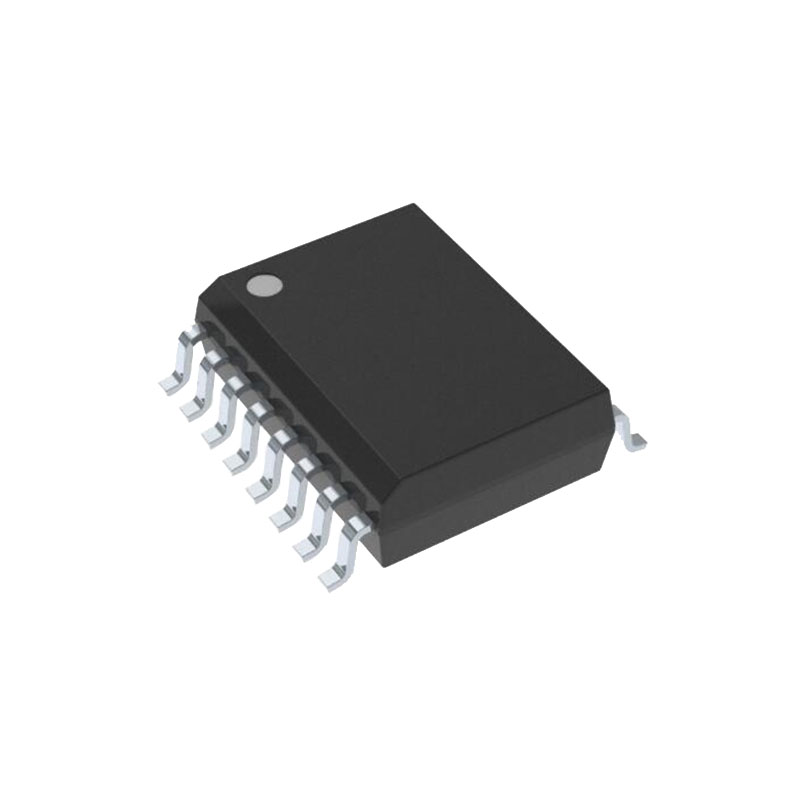
16-lead SOIC wide body package
RoHS-compliant models available
Safety and regulatory approvals
UL recognition: 2500 V rms for 1 minute per UL 1577
CSA Component Acceptance Notice 5A
VDE Certificate of Conformity
DIN V VDE V 0884-10 (VDE V 0884-10):2006-12
VIORM = 560 V peak
TÜV approval: IEC/EN/UL/CSA 61010-1
APPLICATIONS
General-purpose multichannel isolation
SPI interface/data converter isolation
RS-232/RS-422/RS-485 transceivers
Industrial field bus isolation
Automotive systems
PROPAGATION DELAY-RELATED PARAMETERS
Channel-to-channel matching refers to the maximum amount the propagation delay differs between channels within a single ADuM1400/ADuM1401/ADuM1402 component.
Propagation delay skew refers to the maximum amount the propagation delay differs between multiple ADuM1400/ ADuM1401/ADuM1402 components operating under the same conditions.
DC CORRECTNESS AND MAGNETIC FIELD IMMUNITY
Positive and negative logic transitions at the isolator input cause narrow (~1 ns) pulses to be sent to the decoder via the transformer. The decoder is bistable and is, therefore, either set or reset by the pulses, indicating input logic transitions. In the absence of logic transitions at the input for more than ~1 µs, a periodic set of refresh pulses indicative of the correct input state are sent to ensure dc correctness at the output. If the decoder receives no internal pulses of more than about 5 µs, the input side is assumed to be unpowered or nonfunctional, in which case the isolator output is forced to a default state by the watchdog timer circuit.
The limitation on the magnetic field immunity of the ADuM1400/ ADuM1401/ADuM1402 is set by the condition in which induced voltage in the receiving coil of the transformer is sufficiently large enough to either falsely set or reset the decoder. The following analysis defines the conditions under which this may occur. The 3 V operating condition of the ADuM1400/ADuM1401/ ADuM1402 is examined because it represents the most susceptible mode of operation.

