GENERAL DESCRIPTION
The ADuM7440 are 4-channel digital isolators based on the Analog Devices, Inc., iCoupler® technology.
Combining high speed CMOS and monolithic air core transformer technologies, these isolation components provide outstanding performance characteristics superior to the alternatives, such as optocoupler devices and other integrated couplers.
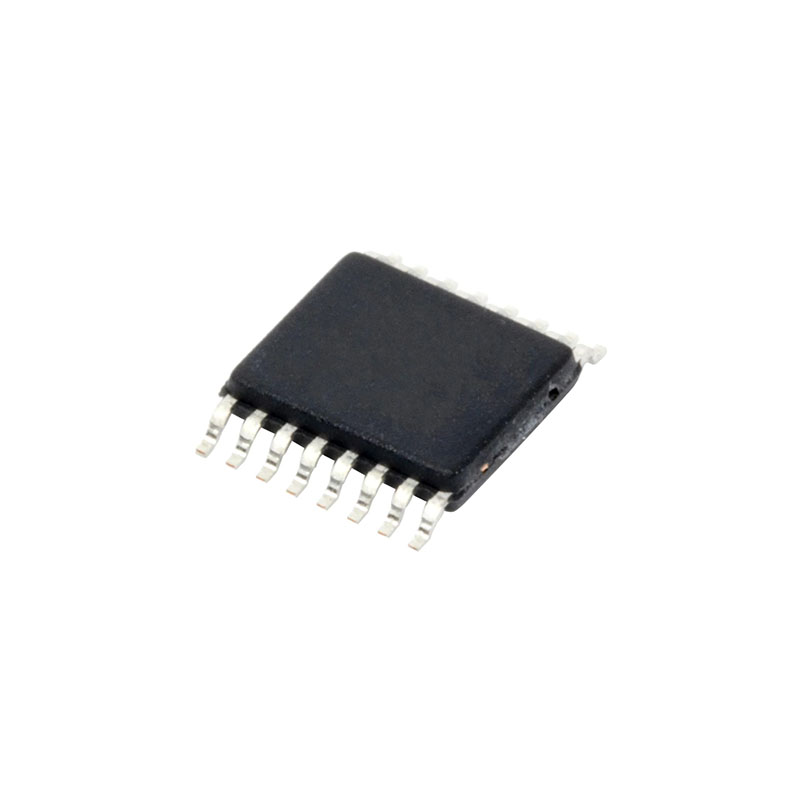
The ADuM7440 family of quad 1 kV digital isolation devices is packaged in a small 16-lead QSOP. While most 4-channel isolators come in 16-lead wide SOIC packages, the ADuM7440 frees almost 70% of board space and yet can still withstand high isolation voltage and meet regulatory requirements such as UL and CSA standards (pending).
In addition to the space savings, the ADuM7440 offers a lower price than 2.5 kV or 5 kV isolators where only functional isolation is needed.
This family, like many Analog Devices isolators, offers very low power consumption, consuming one-tenth to one-sixth the power of comparable isolators at comparable data rates up to 25 Mbps. Despite the low power consumption, all models of the ADuM7440 provide low pulse width distortion (< 5 ns for C grade). In addition, every model has an input glitch filter to protect against extraneous noise disturbances.
The ADuM7440 isolators provide four independent isolation channels in a variety of channel configurations and two data rates (see the Ordering Guide) up to 25 Mbps. All models operate with the supply voltage on either side ranging from 3.0 V to 5.5 V, providing compatibility with lower voltage systems as well as enabling voltage translation functionality across the isolation barrier. All products also have an output default high logic state in the absence of the input power.
FEATURES
Small, 16-lead QSOP
1000 V rms isolation rating
Safety and regulatory approvals
Low power operation
5 V operation
2.25 mA per channel maximum at 0 Mbps to 1 Mbps
11.5 mA per channel maximum at 25 Mbps
3.3 V operation
1.5 mA per channel maximum at 0 Mbps to 1 Mbps
8.25 mA per channel maximum at 25 Mbps
Bidirectional communication
Up to 25 Mbps data rate (NRZ)
3 V/5 V level translation
High temperature operation: 105°C
High common-mode transient immunity: >15 kV/μs
APPLICATIONS
General-purpose, multichannel isolation
SPI interface/data converter isolation
RS-232/RS-422/RS-485 transceivers
Industrial field bus isolation
APPLICATIONS INFORMATION
PC BOARD LAYOUT
The ADuM7440 digital isolators require no external interface circuitry for the logic interfaces. Power supply bypassing is strongly recommended at the input and output supply pins. A total of four bypass capacitors should be connected between Pin 1 and Pin 2 for VDD1A, between Pin 7 and Pin 8 for VDD1B, between Pin 9 and Pin 10 for VDD2B, and between Pin 15 and Pin 16 for VDD2A. Supply VDD1A Pin 1 and VDD1B Pin 7 should be connected together and supply VDD2B Pin 10 and VDD2A Pin 16 should be connected together. The capacitor values should be between 0.01 µF and 0.1 µF. The total lead length between both ends of the capacitor and the power supply pin should not exceed 20 mm.
In applications involving high common-mode transients, it is important to minimize board coupling across the isolation barrier. Furthermore, users should design the board layout so that any coupling that does occur equally affects all pins on a given component side. Failure to ensure this can cause voltage differentials between pins exceeding the absolute maximum ratings of the device, thereby leading to latch-up or permanent damage.
PROPAGATION DELAY-RELATED PARAMETERS
Propagation delay is a parameter that describes the time it takes a logic signal to propagate through a component. The input-to-output propagation delay time for a high-to-low transition may differ from the propagation delay time of a low-to-high transition.
Pulse width distortion is the maximum difference between these two propagation delay values and an indication of how accurately the timing of the input signal is preserved.