DESCRIPTION
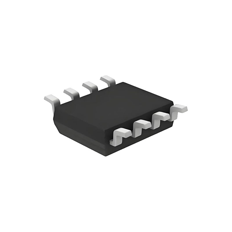
The LTC4211 is a hot swap controller that allows a board to be safely inserted and removed from a live backplane. An internal high side switch driver controls the gate of an external N-channel MOSFET for supply voltages ranging from 2.5V to 16.5V. The LTC4211 provides soft-start and inrush current limiting during the start-up period which has a programmable duration.
Two on-chip current limit comparators provide dual level overcurrent circuit breaker protection. The slow comparator trips at VCC – 50mV and activates in 20μs (or is programmed by an external filter capacitor, MS only). The fast comparator trips at VCC – 150mV and typically responds in 300ns.
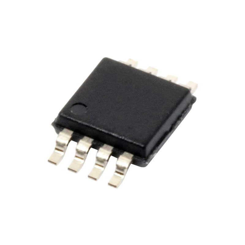
The FB pin monitors the output supply voltage and signals the RESET output pin. The ON pin signal turns the chip on and off and can also be used for the reset function. The MS package has FAULT and FILTER pins to provide additional functions like fault indication, autoretry or latch-off modes, programmable current limit response time and programmable overvoltage protection using an external Zener diode clamp.
FEATURES
Allows Safe Board Insertion and Removal from a Live Backplane
Controls Supply Voltages from 2.5V to 16.5V
Programmable Soft-Start with Inrush Current Limiting, No External Gate Capacitor Required
Faster Turn-Off Time Because No External Gate Capacitor is Required
Dual Level Overcurrent Fault Protection
Programmable Response Time for Overcurrent Protection (MS)
Programmable Overvoltage Protection (MS)
Automatic Retry or Latched Mode Operation (MS)
High Side Drive for an External N-Channel FET
User-Programmable Supply Voltage Power-Up Rate
FB Pin Monitors VOUT and Signals RESET
Glitch Filter Protects Against Spurious RESET Signal
APPLICATIONS
Electronic Circuit Breaker
Hot Board Insertion and Removal (Either On Backplane or On Removable Card)
Industrial High Side Switch/Circuit Breaker
OPERATION
HOT CIRCUIT INSERTION
When circuit boards are inserted into or removed from live backplanes, the supply bypass capacitors can draw huge transient currents from the backplane power bus as they charge. The transient current can cause permanent damage to the connector pins as well as cause glitches on the system supply, causing other boards in the system to reset.
The LTC4211 is designed to turn a printed circuit board’s supply voltages ON and OFF in a controlled manner, allowing the circuit board to be safely inserted or removed from a live backplane. The device provides a system reset signal to indicate when board supply voltage drops below a predetermined level, as well as a dual function fault monitor.
OUTPUT VOLTAGE MONITOR
The LTC4211 uses a 1.236V bandgap reference, precision voltage comparator and an external resistive divider to monitor the output supply voltage.
The operation of the supply monitor in normal mode is illustrated in Figure 2. When the voltage at the FB pin drops below its reset threshold (1.236V), the comparator COMP2 output goes high. After a glitch filter delay, RESET is pulled low (Time Point 1). When the voltage at the FB pin rises above its reset threshold (1.239V), COMP2’s output goes low and a timing cycle starts (Time Point 4). After a complete timing cycle, RESET is pulled high by the external pull-up resistor. If the FB pin rises above the reset threshold for less than a timing cycle, the RESET output remains low (Time Points 2 to 3).
The LTC4211’s RESET pin is logic low during any undervoltage lockout condition and during the initial insertion of a PC board. Under normal operation, RESET goes to logic high at the end of the soft-start cycle only after the FB pin voltage rises above its reset threshold of 1.239V.
UNDERVOLTAGE LOCKOUT
The LTC4211’s power-on reset circuit initializes the startup procedure and ensures the chip is in the proper state if the input supply voltage is too low. If the supply voltage falls below 2.18V, the LTC4211 is in undervoltage lockout (UVLO) mode, and the GATE pin is pulled low. Since the UVLO circuitry uses hysteresis, the chip restarts after the supply voltage rises above 2.3V and the ON pin goes high.
In addition, users can utilize the ON comparator (COMP1) or the FAULT comparator (COMP6) to effectively program a higher undervoltage lockout level. Figure 3 shows how the external resistive divider at the ON pin programs the system’s undervoltage lockout voltage. The system will enter the plug-in cycle after the ON pin rises above 1.316V. The resistive divider sets the circuit to turn on when VCC reaches around 79% of its final value. If a different turn on VCC voltage is desired change the resistive divider values accordingly. Alternatively, the FAULT comparator can be used to configure the external undervoltage lockout level. If the FAULT comparator is used for this purpose, the system will wait for the input voltage to increase above the level set by the user before starting the second timing cycle. Also, if the input voltage drops below the set level in normal operating mode, the user must cycle the ON pin or VCC to restart the system.

