DESCRIPTION
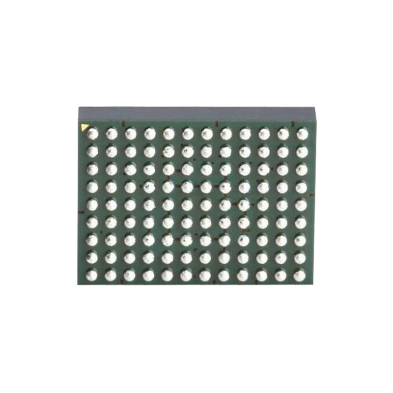
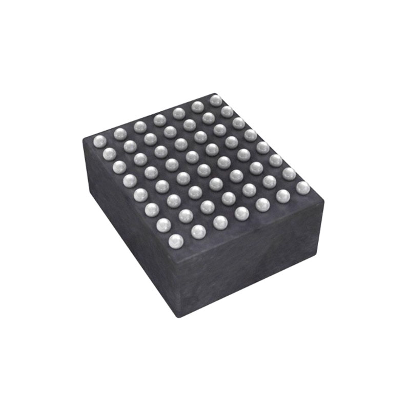
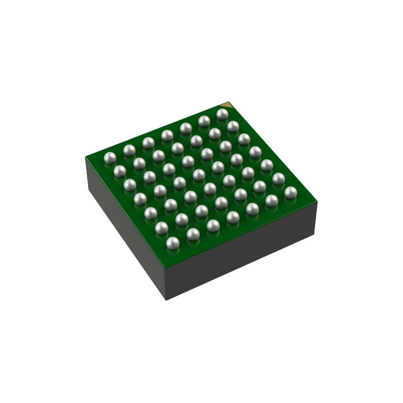
The LTM4668A is a quad DC/DC step-down µModule (micromodule) regulator with 1.2A DC current per output. Outputs can be paralleled in an array for up to 4.8A capability. Included in the package are the switching controllers, power FETs, inductors and support components. Operating over an input voltage range of 2.7V to 17V, the LTM4668A supports an output voltage range of 0.6V to 5.5V. Only bulk input and output capacitors are needed. The device supports frequency synchronization, PolyPhase operation, selectable Burst Mode operation, 100% duty cycle and low IQ operation. Its high switching frequency and a current mode architecture enables a very fast transient response to line and load changes without sacrificing stability. Fault protection features include overvoltage, overcurrent and overtemperature protection. The power module is offered in a space saving and thermally enhanced 6.25mm × 6.25mm × 2.1mm BGA package. The LTM4668A is available with SnPb (BGA) or RoHS-compliant terminal finish.
FEATURES
Quad Output Step-Down µModule Regulator with 1.2A per Output Channel
Wide Input Voltage Range: 2.7V to 17V
0.6V to 5.5V Output Voltage
1.2A DC, Parallelable, Output Current Each Channel
±1.5% Total Output Voltage Regulation
100% Duty Cycle Operation
Current Mode Control, Fast Transient Response
External Frequency Synchronization
Selectable Burst Mode® Operation
Power Good Indicator
Over Voltage, Current and Temperature Protection
6.25mm × 6.25mm × 2.1mm BGA Package
Pin Compatible with LTM4668 (0.6V to 1.8V Output, 1MHz).
APPLICATIONS
Telecom, Networking and Industrial Equipment
Multi-Rail Point of Load Regulation
FPGAs, DSPs and ASICs Application
APPLICATIONS INFORMATION
Output Decoupling Capacitors
With an optimized high frequency, high bandwidth design, only single piece of low ESR output ceramic capacitor is required for each regulator channel to achieve low output voltage ripple and very good transient response. Additional output filtering may be required by the system designer, if further reduction of output ripples or dynamic transient spikes is required. Table 8 shows a matrix of different output voltages and output capacitors to minimize the voltage droop and overshoot during a 0.3A (25%) load step transient. Multiphase operation will reduce effective output ripple as a function of the number of phases. Application Note 77 discusses this noise reduction versus output ripple current cancellation, but the output capacitance will be more a function of stability and transient response. The LTpowerCAD design tool is available to download online for output ripple, stability and transient response analysis and calculating the output ripple reduction as the number of phases implemented increases by N times.
Burst Mode Operation
The LTM4668A is capable of Burst Mode operation in which the power MOSFETs operate intermittently based on load demand, thus saving quiescent current. For applications where maximizing the efficiency at very light loads is a high priority, Burst Mode operation should be applied. To enable Burst Mode operation, simply tie the MODE/ SYNC pin to INTVCC. During Burst Mode operation, the peak current of the inductor is set to approximately 400mA in normal operation even though the output of the error amplifier (COMP) indicates a lower value. The COMP voltage drops when the inductor’s average current is greater than the load requirement. As the COMP voltage drops below 0.2V, the burst comparator trips, causing the internal sleep line to go high and turn off both power MOSFETs. In sleep mode, the internal circuitry is partially turned off, reducing the quiescent current. The load current is now being supplied from the output capacitors. When the output voltage drops, causing COMP voltage to rise, the internal sleep line goes low, and the LTM4668A resumes normal operation. The next oscillator cycle will turn on the top power MOSFET and the switching cycle repeats. When all channels are in sleep mode, the LTM4668A module draws only 8µA of quiescent current from VIN.