DESCRIPTION
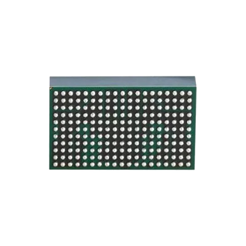
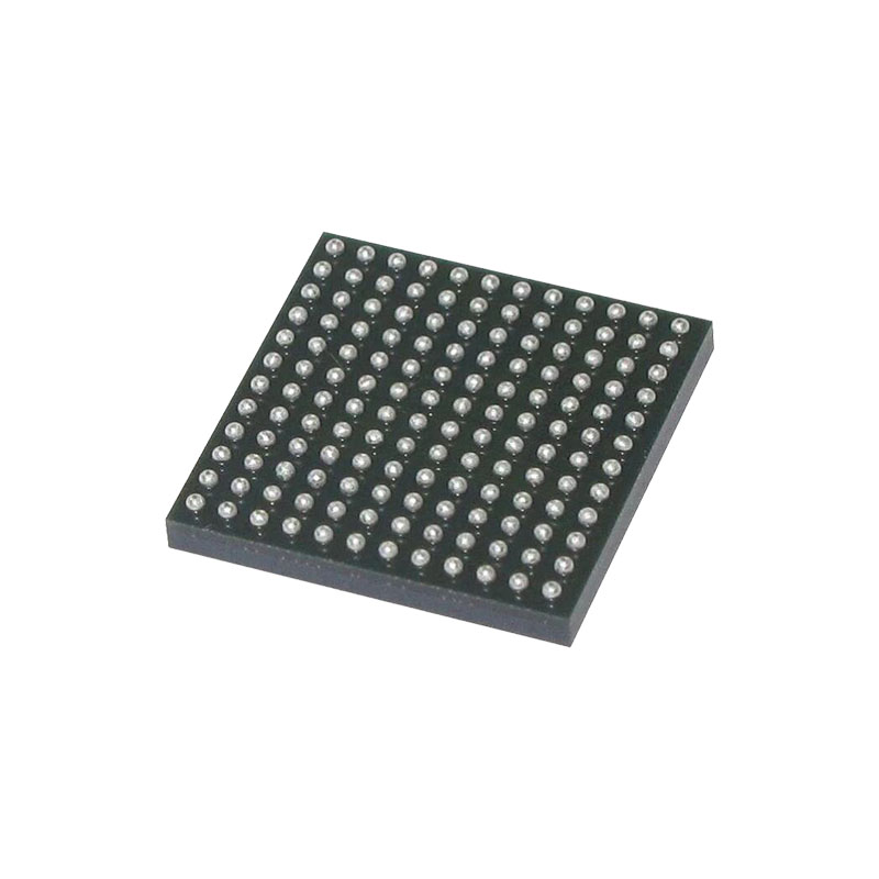
The LTM4671 is a quad DC/DC step-down µModule (micromodule) regulator offering dual 12A and dual 5A output. Included in the package are the switching controllers, power FETs, inductors and support components. Operating over an input voltage range of 3.1V to 20V, the LTM4671 supports an output voltage range of 0.6V to 3.3V for two 12A channels and 0.6V to 5.5V for two 5A channels, each set by a single external resistor. Only bulk input and output capacitors are needed. Fault protection features include overvoltage, overcurrent and overtemperature protection. The LTM4671 is offered in 9.5mm × 16mm × 4.72mm BGA package.
FEATURES
Quad Output Step-Down µModule® Regulator with Dual 12A and Dual 5A Output
Wide Input Voltage Range: 3.1V to 20V
Dual 12A DC Output from 0.6V to 3.3V
Dual 5A DC Output from 0.6V to 5.5V
Up to 7W Power Dissipation (TA = 60°C, 200LFM, No Heat Sink)
±1.5% Total Output Voltage Regulation
Dual Differential Sensing Amplifier
Current Mode Control, Fast Transient Response
Parallelable for Higher Output Current
Selectable Burst Mode® Operation
Output Voltage Tracking
Internal Temperature Sensing Diode Output
External Frequency Synchronization
Overvoltage, Current and Temperature Protection
9.5mm × 16mm × 4.72mm BGA Package
APPLICATIONS
Multirail Point-of-Load Regulation
FPGAs, DSPs and ASICs Applications
OPERATION
The LTM4671 is a quad output standalone non-isolated switch mode DC/DC power supply. It has built-in four separate regulator channels which can deliver 12A, 12A, 5A, 5A continuous output current with few external input and output capacitors. Two 12A regulator provides precisely regulated output voltage programmable from 0.6V to 3.3V via a single external resistor over 3.1V to 20V input voltage range while the other two 5A regulator can support output voltage from 0.6V to 5.5V. Dual true differential remote sensing amplifiers are included in the high current channels to get accurate regulation at load point.
The LTM4671 has integrated four separate constant ontime valley current mode regulators, power MOSFETs, inductors, and other supporting discrete components. For switching noise-sensitive applications, the switching frequency can be adjusted by external resistors and the µModule can be externally synchronized to a clock. See the Applications Information section.
With current mode control and internal feedback loop compensation, the LTM4671 module has sufficient stability margins and good transient performance with a wide range of output capacitors, even with all ceramic output capacitors. For Dual 12A output rails, an optional Type II C-R-C external compensation network is allowed to customize the stability and transient performance.
Current mode control also provides cycle-by-cycle fast current monitoring. An internal overvoltage and undervoltage comparators pull the open-drain PGOOD output low if the output feedback voltage exits a ±10% window around the regulation point. Furthermore, in an overvoltage condition, internal top FET is turned off and bottom FET is turned on and held on until the overvoltage condition clears.
APPLICATIONS INFORMATION
With an optimized high frequency, high bandwidth design, only single piece of low ESR output ceramic capacitor is required for each regulator channel to achieve low output voltage ripple and very good transient response. Additional output filtering may be required by the system designer, if further reduction of output ripples or dynamic transient spikes is required. Table 3 shows a matrix of different output voltages and output capacitors to minimize the voltage droop and overshoot during a 25% load step transient. Multiphase operation will reduce effective output ripple as a function of the number of phases. Application Note 77 discusses this noise reduction versus output ripple current cancellation, but the output capacitance will be more a function of stability and transient response. The Analog Devices LTpowerCAD Design Tool is available to download online for output ripple, stability and transient response analysis and calculating the output ripple reduction as the number of phases implemented increases by N times.

