DESCRIPTION
The LTM8064 is a 58VIN, 6A, constant-voltage, constant current (CVCC), step-down µModule (micromodule) regulator. Included in the package is the switching controller, the power switches, an inductor and the supported components. Operating over an input voltage range of 6V to 58V, the LTM8064 supports an output voltage range of 1.2V to 36V. The CVCC operation allows the LTM8064 to accurately regulate its output current up to 7A when sourcing and 9.1A when sinking over the entire output range. The output current can be set by a control voltage, a single resistor, or a thermistor. To set the switching frequency, simply place a resistor from the RT pin to ground. A resistor from FB to ground will set the output voltage. Only bulk input and output filter capacitors are needed to finish the design.
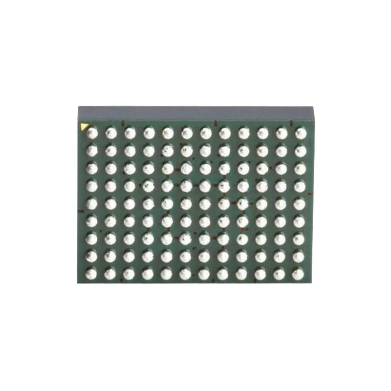
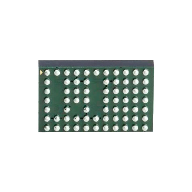
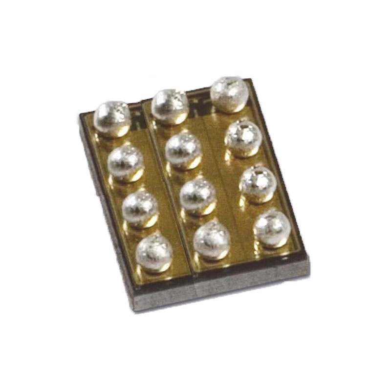
The LTM8064 is packaged in a thermally enhanced, compact (16mm × 11.9mm × 4.92mm) over-molded ball grid array (BGA) package suitable for automated assembly by standard surface mount equipment. The LTM8064 is RoHS compliant.
FEATURES
Complete Step-Down Switch Mode Power Supply
CVCC: Constant Voltage, Constant Current
2-Quadrant: Sources and Sinks Output Current
Parallelable for Increased Output Current, Even from Different Voltage Sources
Adjustable Output Current Up to 7A When Sourcing or 9.1A When Sinking
Wide Input Voltage Range: 6V to 58V
1.2V to 36V Output Voltage
Selectable Switching Frequency: 100kHz to 1MHz
(e1) RoHS-Compliant Package
Programmable Soft-Start
Tiny (16mm × 11.9mm × 4.92mm) Surface-Mount BGA Package
APPLICATIONS
Short-Circuit Protection or Accurate Output Current Limit
High Power LED Driver
Peltier Driver
Motor Driver
Battery/Supercapacitor Charging and Cell Balancing
APPLICATIONS INFORMATION
The design process is summarized as follows:
- Look at Table 1 and find the row that has the desired input range and output voltage.
- Apply the recommended CIN, COUT, RFB and RT values.
While these component combinations have been tested for proper operation, it is necessary for the user to verify proper operation over the intended system’s input voltage, load and environmental conditions. The maximum output current is limited by junction temperature, the relationship between the input and output voltage magnitude and polarity and other factors. See the graphs in the Typical Performance Characteristics section for guidance. There are additional conditions that must be satisfied if the synchronization function is used. See the Switching Frequency Synchronization section for details. Using larger values may yield improved dynamic response, but using values that are too large may also result in undesirable operation.Ceramic capacitors are small, robust and have very low ESR. However, not all ceramic capacitors are suitable. X5R and X7R types are stable over temperature and applied voltage and give dependable service. Other types, including Y5V and Z5U have very large temperature and voltage coefficients of capacitance. In an application circuit they may have only a small fraction of their nominal capacitance resulting in much higher output voltage ripple than expected.
Ceramic capacitors may also be used in the application, but it may be necessary to use more of them. Many high value ceramic capacitors have a large voltage coefficient, so the actual capacitance of the component at the desired operating voltage may be only a fraction of the specified value. Very low ESR of ceramic capacitors may necessitate additional capacitors for acceptable stability margin. For a more detailed explanation of this, see Analog Devices Applications Note 104. A ceramic capacitor at the input of the LTM8064 combined with input trace or cable inductance can form a high Q (underdamped) tank circuit. If the LTM8064 circuit is hot-plugged into a supply, the input voltage can ring to twice its nominal value, possibly exceeding the device’s rating. This situation is easily avoided; see the Hot-Plugging Safely section.

