FEATURES
Two Complete Step-Down Switching Power Supplies
Low Noise Silent Switcher® Architecture
CISPR22 Class B Compliant
CISPR25 Class 5 Compliant
Wide Input Voltage Range: 3V to 40V
Wide Output Voltage Range: 0.8V to 10V
1.4A Continuous Output Current per Channel at 24VIN, 3.3VOUT, TA = 85°C
Multiphase Parallel Operation to Increase Current
Selectable Switching Frequency: 300kHz to 3MHz
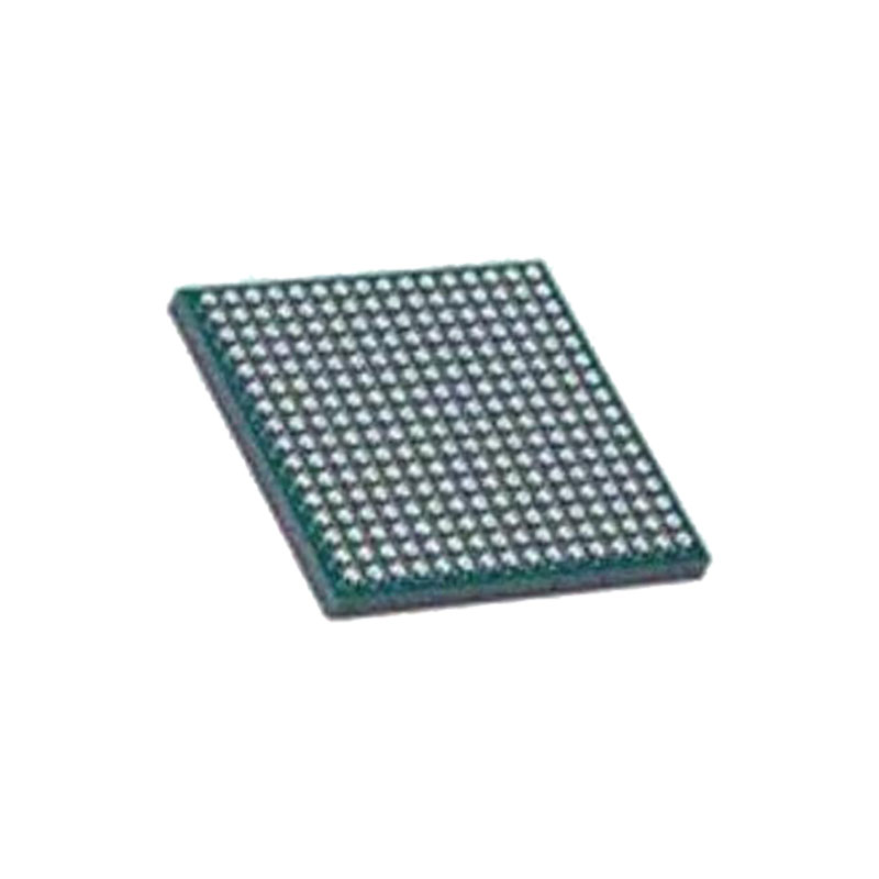
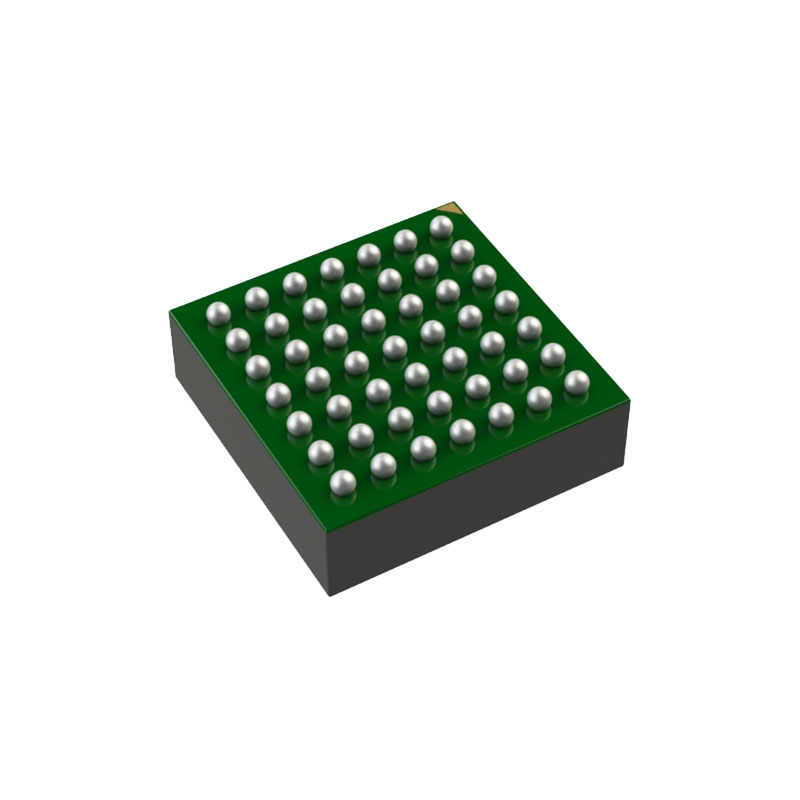
Compact Package (6.25mm × 6.25mm × 2.22mm) Surface Mount BGA
APPLICATIONS
Automated Test Equipment
Distributed Supply Regulation
Industrial Supplies
Medical Equipment
DESCRIPTION
The LTM®8078 is 40VIN, dual 1.4A/single 2.8A step-down Silent Switcher μModule® regulator. The Silent Switcher architecture minimizes EMI while delivering high efficiency at frequencies up to 3MHz. Included in the package are the controllers, power switches, inductors, and support components. Operating over a wide input voltage range, the LTM8078 supports output voltages from 0.8V to 10V, and a switching frequency range of 300kHz to 3MHz, each set by a single resistor. Only the bulk input and output filter capacitors are needed to finish the design. The LTM8078 product video is available on website.
LTM8078#3PP is an AEC-Q104 qualified automotive grade μModule regulator. The production is compliant to Analog Devices automotive assemble flow. All components integrated in the package are AEC-Q100 or AEC-Q200 qualified.
The LTM8078 is packaged in a compact (6.25mm × 6.25mm × 2.22mm) over-molded Ball Grid Array (BGA) package suitable for automated assembly by standard surface mount equipment. The LTM8078 is available with SnPb (BGA) or RoHS compliant.
OPERATION
The LTM8078 is a dual standalone non-isolated step down switching DC/DC power supply that can deliver a peak current of up to 2.5A per channel. The continuous current is determined by the internal operating tempera ture. It provides a precisely regulated output voltage pro grammable via one external resistor from 0.8V to 10V. The input voltage range for channel 1 is 3V to 40V, while the input voltage range for channel 2 is 2V to 40V. VIN1 must be 3V or above for either channel to operate.
Given that the LTM8078 is a step-down converter, make sure that the input voltage is high enough to support the desired output voltage and load current. See simplified Block Diagram. The LTM8078 contains two current mode controllers, power switching elements, power inductors and a modest amount of input and output capacitance. The LTM8078 is a fixed frequency PWM regulator. The switching frequency is set by simply connecting the appropriate resistor value from the RT pin to GND.
An internal regulator provides power to the control cir cuitry. This bias regulator normally draws power from the VIN1 pin, but if the BIAS pin is connected to an external voltage higher than 3.2V, bias power is drawn from the external source (typically the regulated output voltage). This improves efficiency. Tie BIAS to GND if it is not used.
To enhance efficiency, the LTM8078 automatically switches to Burst Mode® operation in light or no load situations. Between bursts, all circuitry associated with controlling the output switch is shut down reducing the input supply current to just a few µA.
The LTM8078 contains a power good comparator which trips when the FBn pin is at about 92% to 108% of its regulated value. The PGn output is an open-drain transis tor that is off when the output is in regulation, allowing an external resistor to pull the PGn pin high. The PG1 signal is valid when VIN1 is above 3V. Similarly, the PG2 signal is valid when VIN2 is above 2V.
The LTM8078 is equipped with a thermal shutdown that inhibits power switching at high junction temperatures. The activation threshold of this function is above the max imum temperature rating to avoid interfering with normal operation, so prolonged or repetitive operation under a condition in which the thermal shutdown activates may damage or impair the reliability of the device.