General Description
The MAX14775E/MAX14776E fault-protected RS-485/RS-422 transceivers feature ±65V protection for overvoltage signal faults on communication bus lines, ensuring communication in harsh industrial environments. Each device contains one driver and one receiver and operates over the 3V to 5.5V supply range. The MAX14775E is optimized for high-speed data rates up to 20Mbps. The MAX14776E features slew-rate limited outputs for data rates up to 500kbps.
These transceivers are optimized for robust communication in noisy environments. A large 200mV (typ) hysteresis on receiver inputs ensure for high noise rejection and a fail safe feature guarantees a logic-high on the receiver output when the inputs are open or shorted. Driver outputs are protected against short-circuit conditions.
The MAX14775E/MAX14776E receivers feature a 1/3unit load input impedance, allowing up to 100 transceivers on a bus.
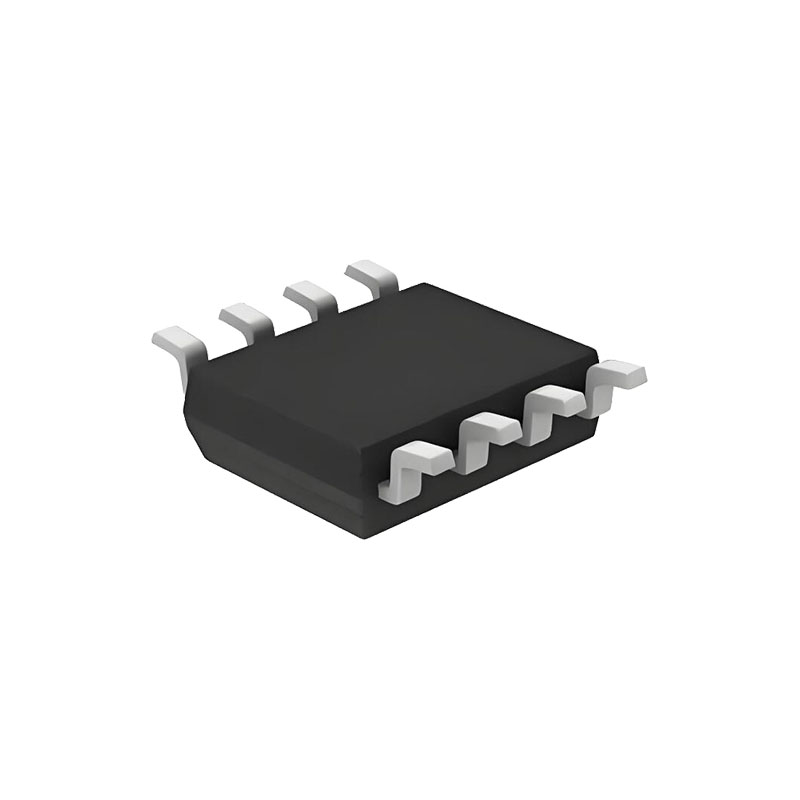
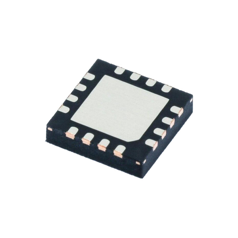
The MAX14775E/MAX14776E are available in 8-pin SOIC and 8-pin TDFN-EP packages and operate over the -40°C to +125°C temperature range.
Benefits and Features
Integrated Protection Ensures for Robust Communication
±65V Fault Protection Range on Driver Outputs/Receiver Inputs
±25V Common Mode Range on the Receiver Inputs
Large Receiver Hysteresis Increases Noise Tolerance
Hot-Swap Protection
Thermal Shutdown
High-Performance Transceiver Enables Flexible Designs
Compliant with RS-485 EIA/TIA-485 Standard
20Mbps (MAX14775E)/500kbps (MAX14776E) Maximum Data Rate
3V to 5.5V Supply Range
Up to 100 Devices on the Bus
Applications
Industrial Field Bus Networks
Motion Controllers
HVAC
Detailed Description
The MAX14775E/MAX14776E half-duplex transceivers are optimized for RS-485/RS-422 applications that require up to ±65V protection from faults on communication bus lines. These devices contain one differential driver and one differential receiver. The devices feature a 1/3 unit
load, allowing up to 100 transceivers on a single bus. The MAX14776E supports data rates up to 500kbps.
Thermal Shutdown Protection
The MAX14775E/MAX14776E feature thermal-shutdown protection circuitry to protect the device. When the junction temperature exceeds +165°C (typ), the driver outputs are disabled and RO is high impedance. Driver and receiver outputs are re-enabled when the junction temperature falls below 150°C (typ).
Hot-Swap Functionality
Hot-Swap Inputs
Inserting circuit boards into a hot, or powered backplane may cause voltage transients on DE, RE, and receiver inputs A and B that can lead to data errors. For example, upon initial circuit board insertion, the processor under- goes a power-up sequence. During this period, the high- impedance state of the output drivers makes them unable to drive the MAX14775E/MAX14776E enable inputs to a defined logic level. Meanwhile, leakage currents of up to 10μA from the high-impedance output, or capacitively coupled noise from VCC or GND, could cause an input to drift to an incorrect logic state. To prevent such a condition from occurring, the MAX14775E/MAX14776E features hot-swap input circuitry on DE and RE to safeguard against unwanted driver activation during hot-swap situations. When VCC rises, an internal pulldown circuit holds DE low and RE high for at least 10μs. After the initial power-up sequence, the internal pulldown/pullup circuitry becomes transparent, resetting the hot-swap tolerable inputs.
Applications Information
100 Transceivers on the Bus
The MAX14775E/MAX14776E transceivers have 0.32unit load receiver, allowing up to 100 MAX14775E/MAX14776E transceivers connected in parallel on a shared communication line. Connect any combination of these devices, and/or other RS-485 devices, for a maximum of 32 unit loads to the line.
Typical Application
The MAX14775E/MAX14776E half-duplex transceivers are designed for bidirectional data communications on multipoint bus transmission lines.To minimize reflections, the bus should be terminated at the receiver inputs in its characteristics impedance, and stub lengths off the main line should be kept as short as possible.
Power Considerations for the MAX14775E/MAX14776E
At high data rates, the power dissipation of an RS-485 transceiver can be high. The power dissipation of a halfduplex transceiver is determined by a number of factors, including:
The data rate
The time that the driver is transmitting
The termination impedance
The power supply voltage
Higher data rates result in higher power dissipation due to switching losses in the transceiver. Switching losses increase even more when capacitance is applied to the A and B pins. External capacitance should be kept to a minimum to help reduce power dissipation at high data rates.
Similarly, the power dissipation in a transceiver is much higher when the driver is transmitting, compared to when the transceiver is receiving. In half-duplex communication, the period of transmission relative to the idle or receiving intervals (i.e., the duty cycle) should be taken into consideration when calculating the average power dissipation.


