General Description
The MAX3095/MAX3096 are rugged, low-power, quad, RS-422/RS-485 receivers with electrostatic discharge (ESD) protection for use in harsh environments. All receiver inputs are protected to ±15kV using IEC 10004-2 Air-Gap Discharge, ±8kV using IEC 1000-4-2 Contact Discharge, and ±15kV using the Human Body Model. The MAX3095 operates from a +5V supply, while the MAX3096 operates from a +3.3V supply. Receiver propagation delays are guaranteed to within ±8ns of a predetermined value, thereby ensuring device-to-device matching across production lots.
Complementary enable inputs can be used to place the devices in a 1nA low-power shutdown mode in which the receiver outputs are high impedance. When active, these receivers have a fail-safe feature that guarantees a logichigh output if the input is open circuit. They also feature a quarter-unit-load input impedance that allows 128 receivers on a bus.
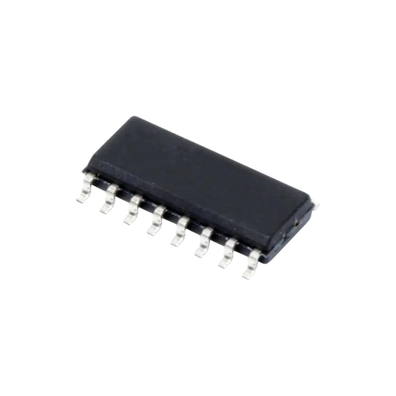
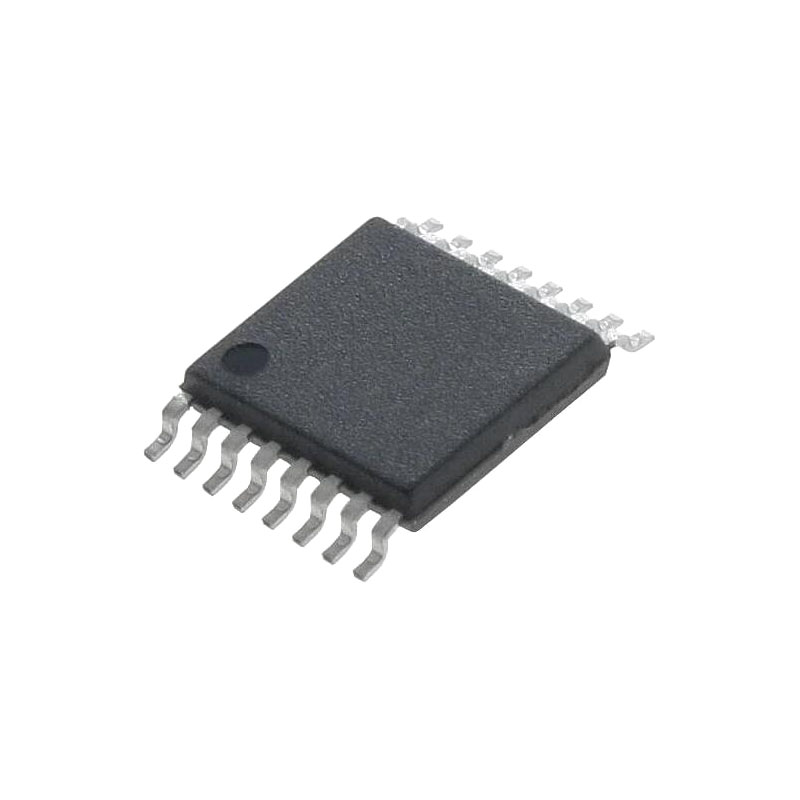
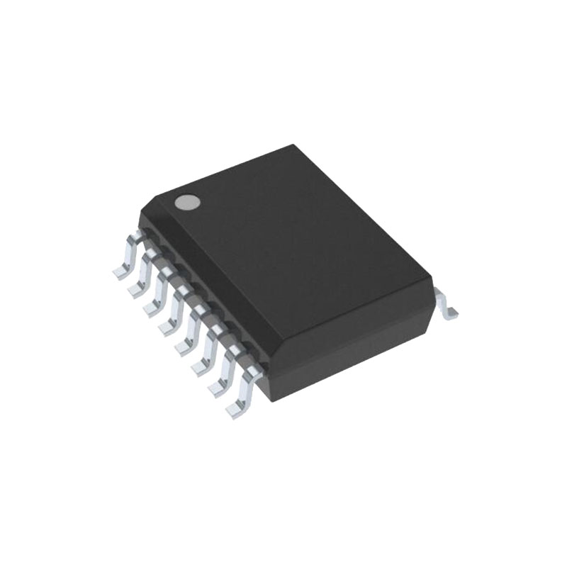
The MAX3095/MAX3096 are pin-compatible, low-power upgrades to the industry-standard ’26LS32. They are available in a space-saving QSOP package.
Applications
Telecommunications Equipment
Rugged RS-422/RS-485/RS-423 Bus Receiver
Receivers for ESD-Sensitive Applications
Level Translators
Features
ESD Protection:
±15kV—IEC 1000-4-2, Air-Gap Discharge
±8kV—IEC 1000-4-2, Contact Discharge
±15kV—Human Body Model
Guaranteed Propagation-Delay Tolerance Between All ICs:
±8ns (MAX3095)
±10ns (MAX3096)
Single +3V Operation (MAX3096) Single +5V Operation (MAX3095)
16-Pin QSOP (8-pin SO footprint)
10Mbps Data Rate
Allow up to 128 Receivers on the Bus
1nA Low-Power Shutdown Mode
2.4mA Operating Supply Current
Pin-Compatible Upgrades to ’26LS32
Detailed Description
±15kV ESD Protection
As with all Maxim devices, ESD-protection structures are incorporated on all pins to protect against electrostatic discharges (ESD) encountered during handling and assembly. The MAX3095/MAX3096 receiver inputs have extra protection against static electricity found in normal operation. Maxim’s engineers developed state-of-the-art structures to protect these pins against ±15kV ESD, without damage. After an ESD event, the MAX3095/MAX3096 continue working without latchup.
ESD protection can be tested in several ways. The receiver inputs are characterized for protection to the following:
1) ±15kV using the Human Body Model
2) ±8kV using the Contact-Discharge Method specified in IEC 1000-4-2 (formerly IEC 801-2)
3) ±15kV using the Air-Gap Method specified in IEC 1000-4-2 (formerly IEC 801-2)
ESD Test Conditions
ESD performance depends on a number of conditions. Contact Maxim for a reliability report that documents test setup, methodology, and results.
IEC 1000-4-2
Since January 1996, all equipment manufactured and/or sold in the European community has been required to meet the stringent IEC 1000-4-2 specification. The IEC 1000-4-2 standard covers ESD testing and performance of finished equipment; it does not specifically refer to integrated circuits. The MAX3095/MAX3096 help you design equipment that meets Level 4 (the highest level) of IEC 1000-4-2, without additional ESD-protection components.
Low-Power Shutdown Mode
The MAX3095/MAX3096 enter shutdown when G is low and G is high. In shutdown, all outputs go high impedance and the devices typically draw less than 1nA. The devices exit shutdown by taking G high or G low. The typical shutdown exit time is 600ns.
Applications Information
Propagation-Delay Matching
The MAX3095/MAX3096 exhibit propagation delays that are closely matched from one device to another, even between devices from different production lots. This feature allows multiple data lines to receive data and clock signals with minimal skewing with respect to each other. The MAX3095 receiver propagation delays are trimmed to a predetermined value ±8ns, while the MAX3096 delays are trimmed to a predetermined value ±10ns.
128 Receivers on the Bus
The standard RS-485 input impedance is 12kΩ (one-unit load). The standard RS-485 transmitter can drive 32 unit loads. The MAX3095/MAX3096 present a 1/4-unit-load input impedance (48kΩ), which allows up to 128 receivers on a bus. Any combination of these RS-485 receivers with a total of 32 unit loads can be connected to the same bus.
Fail-Safe Implementation
The MAX3095/MAX3096 receiver inputs guarantee a logic high output when the inputs are open circuit (no termination resistor used). This occurs when the transmitter is removed from the bus or when all transmitter outputs are high impedance. However, when the line is terminated and the transmitters are disabled, the differential voltage between the A and B inputs falls below the ±200mV RS-485 sensitivity threshold. Consequently, the outputs become undefined. To maintain a fail-safe receiver output while using a terminating resistor, input A must be biased at least 200mV above input B. The resistor-divider network shown in Figure 6 is recommended.

