General Description
The MAX40018 is a dual operational amplifier that consumes only 400nA supply current (per channel). At such low power consumption, the device is ideal for battery-powered applications such as portable medical equipment, portable instruments and wireless handsets.
The MAX40018 operates from a single 1.7V to 5.5V supply, allowing the device to be powered by the same 1.8V, 2.5V, or 3.3V nominal supply that powers the microcontroller. The MAX40018 features rail-to-rail outputs and is unity-gain stable with a 9kHz gain bandwidth product (GBP).
The ultra-low supply current, ultra-low input bias current, low operating voltage, and rail-to-rail output capabilities make this dual operational amplifier ideal for use with single lithium-ion (Li+), or two-cell NiCd or alkaline batteries.
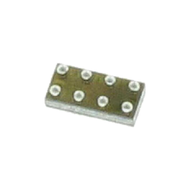
The MAX40018 is available in a tiny, 8-bump, 1.63mm x 0.91mm wafer-level package (WLP), with a bump pitch of 0.4mm, as well as in an 8-pin 3mm x 3mm TDFN package. The device is specified over the -40°C to +125°C, automotive temperature range.
Applications
Wearable Devices
Handheld Devices
Notebook and Tablet Computers
Portable Medical Devices
Portable Instrumentation
Benefits and Features
Ultra-Low Power Preserves Battery Life
400nA Typical Supply Current (Per Channel)
Single 1.7V to 5.5V Supply Voltage Range
The Device Can be Powered From the Same 1.8V/2.5V/3.3V/5V System Rails
Tiny Packages Save Board Space
1.63mm x 0.91mm x 0.5mm WLP-8 with 0.4mm Bump Pitch
3mm x 3mm x 0.75mm TDFN-8 Package
Precision Specifications for Buffer/Filter/Gain Stages
Low 350μV Input Offset Voltage
Rail-to-Rail Output Voltage
9kHz GBP
Low 0.1pA Input Bias Current
Unity-Gain Stable
-40°C to +125°C Temperature Range
Detailed Description
The MAX40018 is a dual operational amplifier that draws just 400nA supply current (typical, per channel). It is ideal for battery-powered applications, such as portable medical equipment, portable instruments, and wireless handsets. The amplifiers feature rail-to-rail outputs and are unity-gain stable with a 9kHz GBP. The ultra-low supply current, ultra-low input bias current, low operating voltage, and rail-to-rail output capabilities make this dual operational amplifier ideal for use with single lithium-ion (Li+), or two-cell NiCd or alkaline batteries.
Power Supplies and PCB Layout
The MAX40018 operates from a single +1.7V to +5.5V power supply, or dual ±0.85V to ±2.75V power supplies. Bypass the power supplies with a 0.1μF ceramic capacitor placed close to VDD and VSS pins. Adding a solid ground plane improves performance generally by decreasing the noise at the op amp’s inputs. However, in very high impedance circuits, it may be worth removing the ground plane under the IN_- pins to reduce the stray capacitance and help avoid reducing the phase margin. To further decrease stray capacitance, minimize PCB trace lengths and resistor and capacitor leads, and place external components close to the amplifier’s pins.
Ground Sensing Inputs
The common-mode voltage range of the MAX40018 extends down to VSS – 0.1V, and offers excellent common-mode rejection. This feature allows input voltage below ground in a single power supply application, where ground sensing is very common. This op amp is also guaranteed not to exhibit phase reversal when either input is overdriven.
Rail-To-Rail Outputs
The outputs of the MAX40018 dual op amps are guaranteed to swing within 8mV of the power supply rails with a 100kΩ load.
Stability
The MAX40018 maintains stability in its minimum gain configuration while driving capacitive loads up to 30pF or so. Larger capacitive loading is achieved using the techniques described in the Capacitive Load Stability section below. Although this amplifier is primarily designed for low frequency applications, good layout can still be extremely important, especially if very high value resistors are being used, as is likely in ultra-low-power circuitry. However, some stray capacitance may be unavoidable; and it may be necessary to add a 2pF to 10pF capacitor across the feedback resistor. Select the smallest capacitor value that ensures stability so that BW and settling time are not significantly impacted.


