General Description
The MAX4194 is a variable-gain precision instrumentation amplifier that combines Rail-to-Rail® single-supply operation, outstanding precision specifications, and a high gain bandwidth. This amplifier is also offered in three fixed-gain versions: the MAX4195 (G = +1V/V), the MAX4196 (G = +10V/V), and the MAX4197 (G = +100V/V). The fixed-gain instrumentation amplifiers feature a shutdown function that reduces the quiescent current to 8µA. A traditional three operational amplifier configuration is used to achieve maximum DC precision.
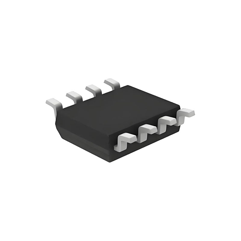
The MAX4194–MAX4197 have rail-to-rail outputs and inputs that can swing to 200mV below the negative rail and to within 1.1V of the positive rail. All parts draw only 93µA and operate from a single +2.7V to +7.5V supply or from dual ±1.35V to ±3.75V supplies. These amplifiers are offered in 8-pin SO packages and are specified for the extended temperature range (-40°C to +85°C).
Applications
Medical Equipment
Thermocouple Amplifier
4–20mA Loop Transmitters
Data-Acquisition Systems
Battery-Powered/Portable Equipment
Transducer Interface
Bridge Amplifier
Benefits and Features
Low Power Consumption Is Ideal for Remote-Sensing and Battery-Powered Applications
- +2.7V Single-Supply Operation
- Low Power Consumption
- 93µA Supply Current
- 8µA Shutdown Current(MAX4195/MAX4196/MAX4197)
Precision Specifications Maximize Sensor Peformance
- High Common-Mode Rejection: 115dB (G = +10V/V)
- Input Common-Mode Range Extends 200mV BelowGND
- Low 50µV Input Offset Voltage (G ≥ +100V/V)
- Low ±0.01% Gain Error (G = +1V/V)
- 250kHz -3dB Bandwidth (G = +1V/V, MAX4194)
- Rail-to-Rail Outputs
Applications Information
Power-Supply Bypassing and Layout
Good layout technique optimizes performance by decreasing the amount of stray capacitance at the instrumentation amplifier’s gain-setting pins. Excess capacitance will produce peaking in the amplifier’s frequency response. To decrease stray capacitance, minimize trace lengths by placing external components as close to the instrumentation amplifier as possible. For best performance, bypass each power supply to ground with a separate 0.1µF capacitor.
Transducer Applications
The MAX4194–MAX4197 instrumentation amplifiers can be used in various signal-conditioning circuits for thermocouples, PT100s, strain gauges (displacement sensors), piezoresistive transducers (PRTs), flow sensors, and bioelectrical applications. shows a simplified example of how to attach four strain gauges (two identical two-element strain gauges) to the inputs of the MAX4194. The bridge contains four resistors, two of which increase and two of which decrease by the same ratio.
With a fully balanced bridge, points A (IN+) and B (IN-) see half the excitation voltage (VBRIDGE). The low impedance (120Ω to 350Ω) of the strain gauges, how ever, could cause significant voltage drop contributions by the wires leading to the bridge, which would cause excitation variations. Output voltage VOUT can be calculated as follows:VOUT = VAB · G
where G = (1 + 50kΩ / RG) is the gain of the instrumentation amplifier.
Since VAB is directly proportional to the excitation, gain errors may occur.
Capacitive-Load Stability
The MAX4194–MAX4197 are stable for capacitive loads up to 300pF. Applications that require greater capacitive-load driving capability can use an isolation resistor between the output and the capacitive load to reduce ringing on the output signal. However, this alternative reduces gain accuracy because RISO forms a potential divider with the load resistor.
Rail-to-Rail Output Stage
The MAX4194–MAX4197’s output stage incorporates a common-source structure that maximizes the dynamic range of the instrumentation amplifier.
The output can drive up to a 25kΩ (tied to VCC/2) resistive load and still typically swing within 30mV of the rails. With an output load of 5kΩ tied to VCC/2, the out put voltage swings within 100mV of the rails.
Shutdown Mode
The MAX4195–MAX4197 feature a low-power shutdown mode. When the shutdown pin (SHDN) is pulled low, the internal amplifiers are switched off and the supply current drops to 8µA typically (Figures 5a, 5b, and 5c).This disables the instrumentation amplifier and puts its output in a high-impedance state. Pulling SHDN high enables the instrumentation amplifier.


