DEVICE OVERVIEW
This document contains device specific information for the PIC16F630/676. Additional information may be found in the PIC Mid-Range Reference Manual , which may be obtained from your local Microchip Sales Representative or downloaded from the Microchip web site. The Reference Manual should be considered a complementary document to this Data Sheet and is highly recommended reading for a better understanding of the device architecture and operation of the peripheral modules.
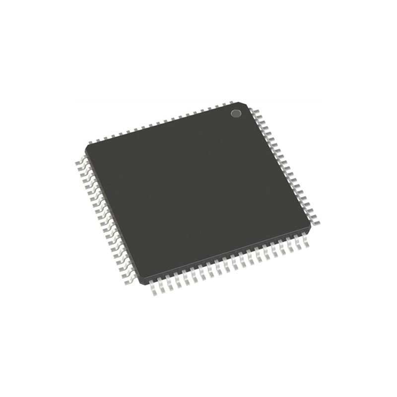
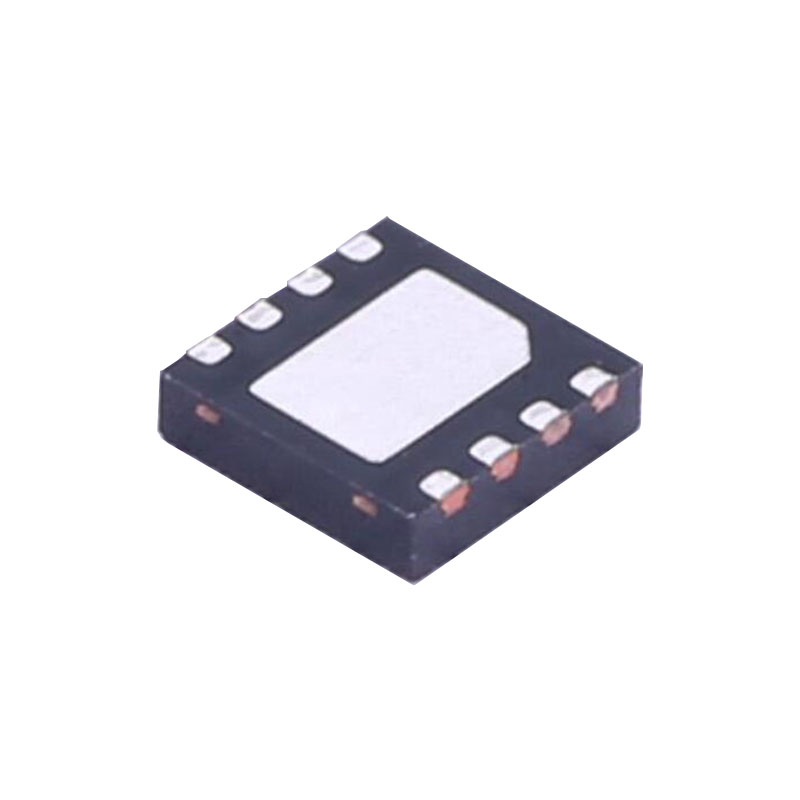
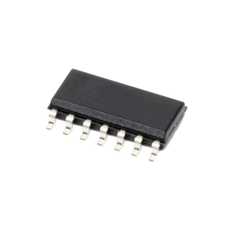
The PIC16F630 and PIC16F676 devices are covered by this Data Sheet. They are identical, except the PIC16F676 has a 10-bit A/D converter. They come in 14-pin PDIP, SOIC and TSSOP packages.
High-Performance RISC CPU:
• Only 35 Instructions to Learn- All single-cycle instructions except branches
• Operating Speed:- DC – 20 MHz oscillator/clock input- DC – 200 ns instruction cycle
• Interrupt Capability
• 8-level Deep Hardware Stack
• Direct, Indirect, and Relative Addressing modes
Special Microcontroller Features:
• Internal and External Oscillator Options
– Precision Internal 4 MHz oscillator factory calibrated to ±1%
– External Oscillator support for crystals and resonators
– 5μs wake-up from Sleep, 3.0V, typical
• Power-Saving Sleep mode
• Wide Operating Voltage Range – 2.0V to 5.5V
• Industrial and Extended Temperature Range
• Low-Power Power-on Reset (POR)
• Power-up Timer (PWRT) and Oscillator Start-up Timer (OST)
• Brown-out Detect (BOD)
• Watchdog Timer (WDT) with Independent Oscillator for Reliable Operation
• Multiplexed MCLR /Input-pin
• Interrupt-on-Pin Change
• Individual Programmable Weak Pull-ups
• Programmable Code Protection
• High Endurance Flash/EEPROM Cell- 100,000 write Flash endurance
– 1,000,000 write EEPROM endurance
– Flash/data EEPROM retention: > 40 years
Low-Power Features:
• Standby Current:
– 1nA @ 2.0V, typical
• Operating Current:
– 8.5μA @ 32 kHz, 2.0V, typical
– 100μA @ 1 MHz, 2.0V, typical
• Watchdog Timer Current
– 300 nA @ 2.0V, typical
• Timer1 Oscillator Current:
– 4μA @ 32 kHz, 2.0V, typical
PORTA and the TRISA Registers
PORTA is an 6-bit wide, bidirectional port. The corresponding data direction register is TRISA. Setting a TRISA bit (= 1) will make the corresponding PORTA pin an input (i.e., put the corresponding output driver in a High-Impedance mode). Clearing a TRISA bit (= 0) will make the corresponding PORTA pin an output (i.e., put the contents of the output latch on the selected pin). The exception is RA3, which is input only and its TRIS bit will always read as ‘1’. Example 3-1 shows how to initialize PORTA.
Reading the PORTA register reads the status of the pins, whereas writing to it will write to the PORT latch. All write operations are read-modify-write operations.Therefore, a write to a port implies that the port pins are read, this value is modified and then written to the PORT data latch. RA3 reads ‘0’ when MCLREN = 1.
Additional Pin Functions
Every PORTA pin on the PIC16F630/676 has an interrupt-on-change option and every PORTA pin, except RA3, has a weak pull-up option. The next two sections describe these functions.
WEAK PULL-UP
Each of the PORTA pins, except RA3, has an individually configurable weak internal pull-up. Control bits WPUAx enable or disable each pull-up. Each weak pull-up is automatically turned off when the port pin is configured as an output. The pull-ups are disabled on a Power-on Reset by the RAPU bit (OPTION<7>).
INTERRUPT-ON-CHANGE
Each of the PORTA pins is individually configurable as an interrupt-on-change pin. Control bits IOCAx enable or disable the interrupt function for each pin. The interrupt-on-change is disabled on a Power-on Reset.
For enabled interrupt-on-change pins, the values are compared with the old value latched on the last read of PORTA. The ‘mismatch’ outputs of the last read are OR’d together to set, the PORTA Change Interrupt flag bit (RAIF) in the INTCON register.
This interrupt can wake the device from Sleep. The user, in the Interrupt Service Routine, can clear the interrupt in the following manner:
a) Any read or write of PORTA. This will end the mismatch condition.
b) Clear the flag bit RAIF.
A mismatch condition will continue to set flag bit RAIF. Reading PORTA will end the mismatch condition and allow flag bit RAIF to be cleared.