ОПИСАНИЕ
The LT1461 is a family of low dropout micropower bandgap references that combine very high accuracy and low drift with low supply current and high output drive. These series references use advanced curvature compensation techniques to obtain low temperature coefficient and trimmed precision thin-film resistors to achieve high output accuracy. The LT1461 family draws only 35μA of supply current, making them ideal for low power and portable applications, however their high 50mA output drive makes them suitable for higher power requirements, such as precision regulators.
In low power applications, a dropout voltage of less than 300mV ensures maximum battery life while maintaining full reference performance. Line regulation is nearly immeasurable, while the exceedingly good load and thermal regulation will not add significantly to system error budgets. The shutdown feature can be used to switch full load currents and can be used for system power down. Thermal shutdown protects the part from overload conditions. The LT1461 is available in 2.5V, 3V, 3.3V 4.096V and 5V options.
ОСОБЕННОСТИ
Trimmed to High Accuracy: 0.04% Max
Low Drift: 3ppm/°C Max
Low Supply Current: 50μA Max
High Output Current: 50mA Min
Low Dropout Voltage: 300mV Max
Excellent Thermal Regulation
Power Shutdown
Тепловое ограничение
All Parts Guaranteed Functional from –40°C to 125°C
Voltage Options: 2.5V, 3V, 3.3V, 4.096V and 5V
AEC-Q100 Qualified for Automotive
Приложения
A/D and D/A Converters
Precision Regulators
Handheld Instruments
Power Supplies
ИНФОРМАЦИЯ О ПРИЛОЖЕНИЯХ
The response of other voltage options can be estimated by proper scaling.
Bypass and Load Capacitors
The LT1461 family requires a capacitor on the input and on the output for stability. The capacitor on the input is a supply bypass capacitor and if the bypass capacitors from other components are close (within 2 inches) they should be sufficient. The output capacitor acts as frequency compensation for the reference and cannot be omitted. For light loads ≤1mA, a 1μF nonpolar output capacitor is usually adequate, but for higher loads (up to 75mA), the output capacitor should be 2μF or greater. The transient response to a 1mA load step with a 1μF output capacitor and a 50mA load step with a 2μF output capacitor.
Precision Regulator
The LT1461 will deliver 50mA with VIN = VOUT + 2.5V and higher load current with higher VIN. Load regulation is typically 12ppm/mA, which means for a 50mA load step, the output will change by only 1.5mV. Thermal regulation, caused by die temperature gradients and created from load current or input voltage changes, is not measurable. This often overlooked parameter must be added to normal line and load regulation errors. The load regulation photo, on the first page of this data sheet, shows the output response to 200mW of instantaneous power dissipation and the reference shows no sign of thermal errors. The reference has thermal shutdown and will turn off if the junction temperature exceeds 150°C.
Выключение
The shutdown (Pin 3 low) serves to shut off load current when the LT1461 is used as a regulator. The LT1461 operates normally with Pin 3 open or greater than or equal to 2.4V. In shutdown, the reference draws a maximum supply current of 35μA. The transient response of shutdown while the part is delivering 25mA. After shutdown, the reference powers up in about 200μs.
PC Board Layout
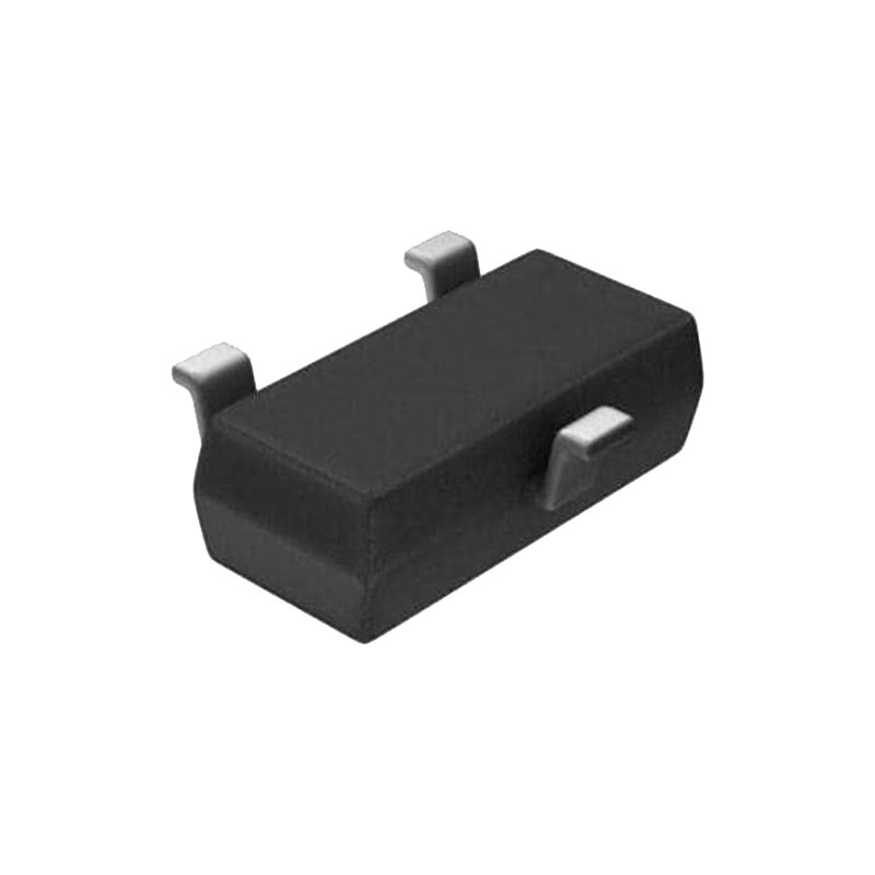
In 13- to 16-bit systems where initial accuracy and temperature coefficient calibrations have been done, the mechanical and thermal stress on a PC board (in a card cage for instance) can shift the output voltage and mask the true temperature coefficient of a reference. In addition, the mechanical stress of being soldered into a PC board can cause the output voltage to shift from its ideal value. Surface mount voltage references are the most susceptible to PC board stress because of the small amount of plastic used to hold the lead frame.
A simple way to improve the stress-related shifts is to mount the reference near the short edge of the PC board, or in a corner. The board edge acts as a stress boundary, or a region where the flexure of the board is minimum. The package should always be mounted so that the leads absorb the stress and not the package. The package is generally aligned with the leads parallel to the long side of the PC board.
A qualitative technique to evaluate the effect of stress on voltage references is to solder the part into a PC board and deform the board a fixed amount. The flexure #1 represents no displacement, flexure #2 is concave movement, flexure #3 is relaxation to no displacement and finally, flexure #4 is a convex movement. This motion is repeated for a number of cycles and the relative output deviation is noted. The parts oriented impart less stress into the package because stress is absorbed in the leads. This corresponds to a 13- to 14-bit system and is not a problem for most 10- to 12-bit systems unless the system has a calibration. In this case, as with temperature hysteresis, this low level can be important and even more careful techniques are required.
The most effective technique to improve PC board stress is to cut slots in the board around the reference to serve as a strain relief. These slots can be cut on three sides of the reference and the leads can exit on the fourth side. This “tongue” of PC board material can be oriented in the long direction of the board to further reduce stress transferred to the reference.