ОСОБЕННОСТИ
Single 3 V supply operation (2.7 V to 3.6 V)
SNR = 70.4 dBc to Nyquist
SFDR = 87.8 dBc to Nyquist
Low power: 366 mW
Differential input with 500 MHz bandwidth
On-chip reference and sample-and-hold
DNL = ±0.4 LSB
Flexible analog input: 1 V p-p to 2 V p-p range
Offset binary or twos complement data format
Clock duty cycle stabilizer
ПРИЛОЖЕНИЯ
High end medical imaging equipment
IF sampling in communications receivers
WCDMA, CDMA-One, CDMA-2000
Battery-powered instruments
Hand-held scopemeters
Low cost digital oscilloscopes
DTV subsystems
ОБЩЕЕ ОПИСАНИЕ
The AD9236 is a monolithic, single 3 V supply, 12-bit, 80 MSPS analog-to-digital converter featuring a high performance sample and-hold amplifier (SHA) and voltage reference. The AD9236 uses a multistage differential pipelined architecture with output error correction logic to provide 12-bit accuracy at 80 MSPS and guarantee no missing codes over the full operating temperature range.
The wide bandwidth, truly differential SHA allows a variety of user-selectable input ranges and common modes, including single-ended applications. It is suitable for multiplexed systems that switch full-scale voltage levels in successive channels and for sampling single-channel inputs at frequencies well beyond the Nyquist rate. Combined with power and cost savings over previously available analog-to-digital converters, the AD9236 is suitable for applications in communications, imaging, and medical ultrasound.
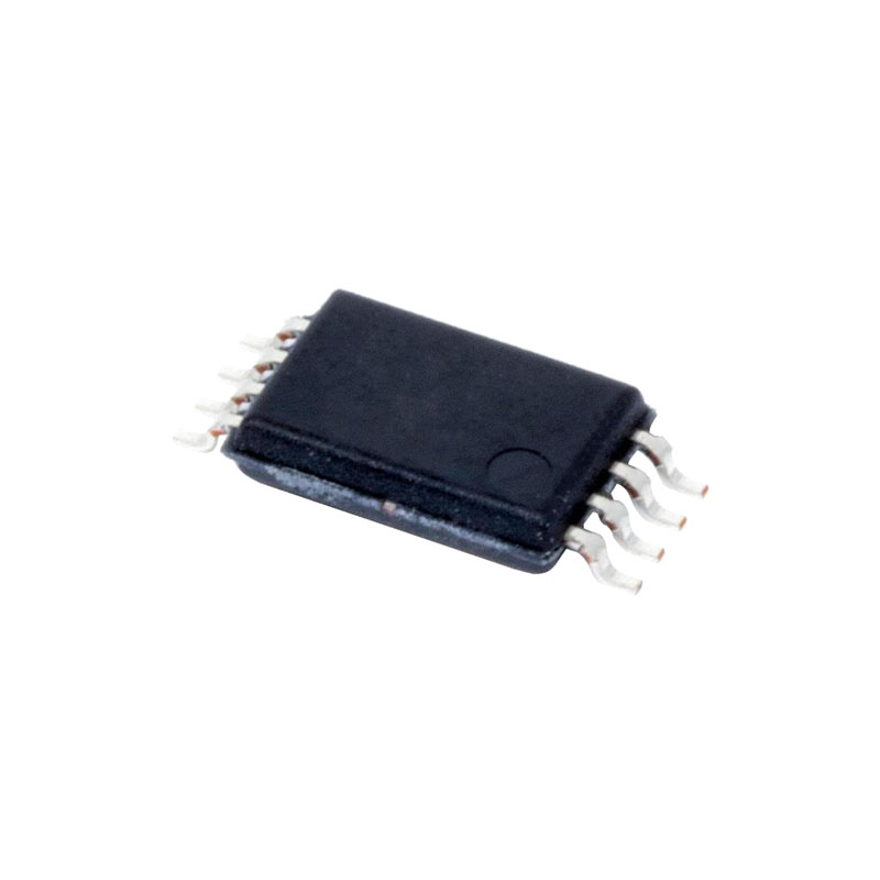
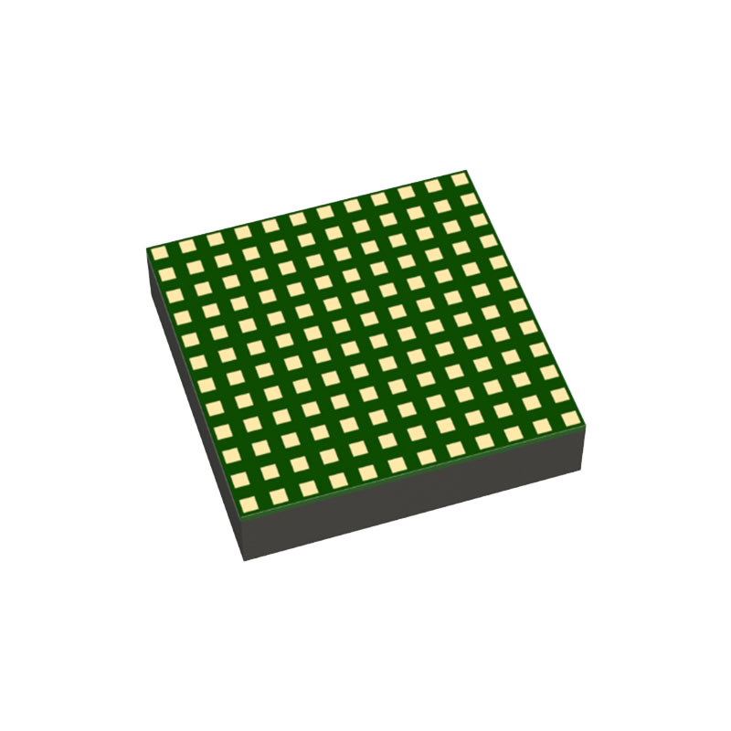
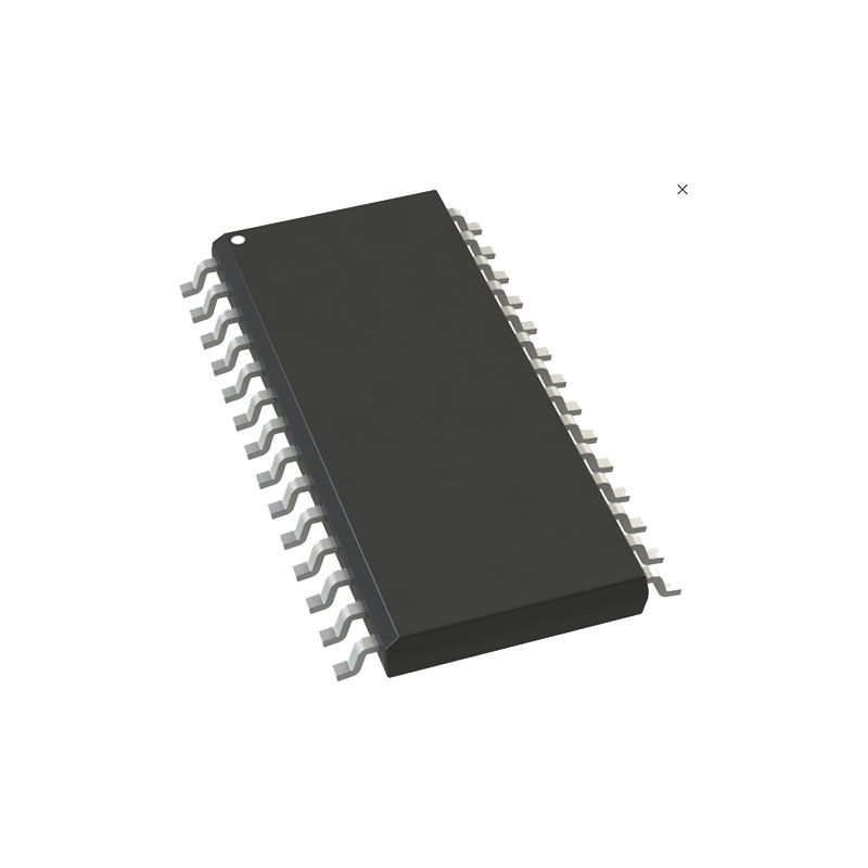
A single-ended clock input is used to control all internal conversion cycles. A duty cycle stabilizer (DCS) compensates for wide variations in the clock duty cycle while maintaining excellent overall ADC performance. The digital output data is presented in straight binary or twos complement formats. An out-of-range (OTR) signal indicates an overflow condition that can be used with the most significant bit to determine low or high overflow. Fabricated on an advanced CMOS process, the AD9236 is available in a 28-lead TSSOP and a 32-lead LFCSP and is specified over the industrial temperature range (−40°C to +85°C).
ОСНОВНЫЕ ХАРАКТЕРИСТИКИ ПРОДУКЦИИ
- The AD9236 operates from a single 3 V power supply and features a separate digital output driver supply to accommodate 2.5 V and 3.3 V logic families.
- Operating at 80 MSPS, the AD9236 consumes a low 366 mW.
- The patented SHA input maintains excellent performance for input frequencies up to 100 MHz, and can be configured for single-ended or differential operation.
- The AD9236 is pin compatible with the AD9215, AD9235, and AD9245. This allows a simplified migration from 10 bits to 14 bits and 20 MSPS to 80 MSPS.
- The DCS maintains overall ADC performance over a wide range of clock pulse widths.
- The OTR output bit indicates when the signal is beyond the selected input range.
ТЕОРИЯ ЭКСПЛУАТАЦИИ
The AD9236 architecture consists of a front-end sample-and hold amplifier (SHA) followed by a pipelined switched capacitor ADC. The pipelined ADC is divided into three sections, consisting of a 4-bit first stage followed by eight 1.5-bit stages and a final 3-bit flash. Each stage provides sufficient overlap to correct for flash errors in the preceding stages. The quantized outputs from each stage are combined into a final 12-bit result in the digital correction logic. The pipelined architecture permits the first stage to operate on a new input sample, while the remaining stages operate on preceding samples. Sampling occurs on the rising edge of the clock.
Each stage of the pipeline, excluding the last, consists of a low resolution flash ADC connected to a switched capacitor DAC and interstage residue amplifier (MDAC). The residue amplifier magnifies the difference between the reconstructed DAC output and the flash input for the next stage in the pipeline. One bit of redundancy is used in each stage to facilitate digital correction of flash errors. The last stage simply consists of a flash ADC.
The input stage contains a differential SHA that can be ac- or dc-coupled in differential or single-ended modes. The output staging block aligns the data, carries out the error correction, and passes the data to the output buffers. The output buffers are powered from a separate supply, allowing adjustment of the output voltage swing. During power-down, the output buffers go into a high impedance state.