Общее описание
The MAX202E-MAX213E, MAX232E, and MAX241E are a family of RS-232 and V.28 transceivers with high ±15kV ESD HBM protection and integrated charge pump circuitry for single +5V supply operation. The various combinations of features are outlined in the Selector Guide. The drivers and receivers for all ten devices meet all EIA/TIA-232E and CCITT V.28 specifications at data rates up to 120kbps when loaded.
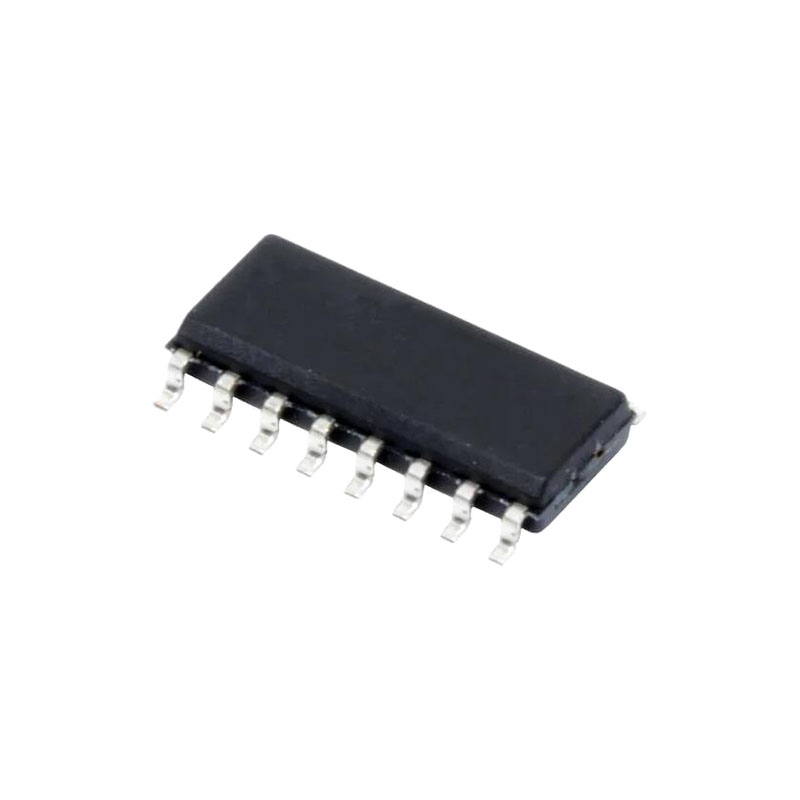
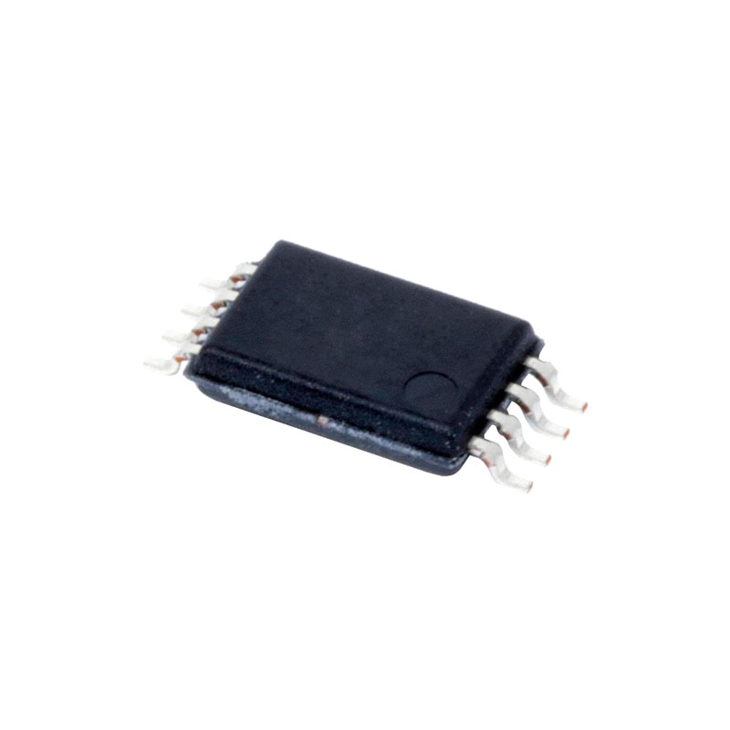
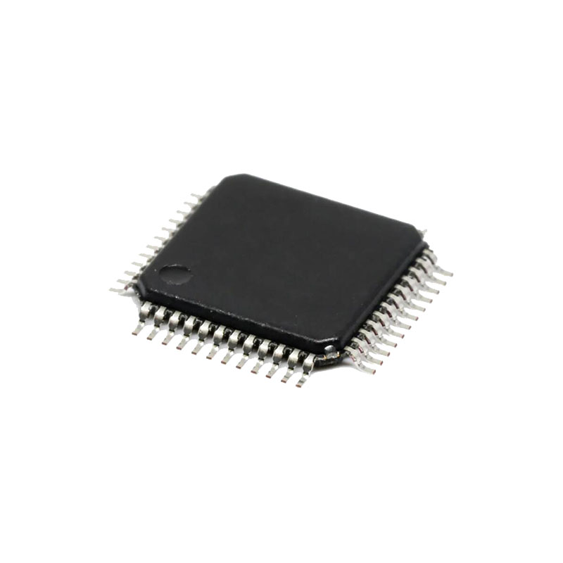
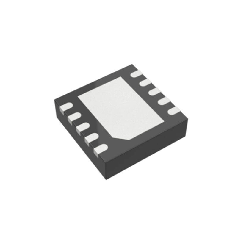
The MAX211E/MAX213E/MAX241E are available in 28-pin SO and SSOP packages. The MAX202E/MAX232E come in 16-pin TSSOP, narrow SO, wide SO, and DIP packages. The MAX203E comes in a 20-pin DIP/SO package, and needs no external charge-pump capacitors. The MAX205E comes in a 24-pin wide DIP package, and also eliminates external charge-pump capacitors.
Приложения
Battery-Powered Equipment
Hand-Held Equipment
Portable Diagnostics Equipment
Benefits and Features
Saves Board Space
Integrated High ±15kV HBM ESD Protection
Integrated Charge Pump Circuitry- Eliminates the Need for a Bipolar ±12V Supply- Enables Single Supply Operation From +5V Supply
Integrated 0.1μF Capacitors (MAX203E, MAX205E)
24 pin SSOP Package Saves up to 40% Versus SO Package
Saves Power for Reduced Power Requirements
1μA Shutdown Mode
15μA Shutdown Mode for MAX213E
Подробное описание
The MAX202E–MAX213E, MAX232E/MAX241E consist of three sections: charge-pump voltage converters, drivers (transmitters), and receivers. These E versions provide extra protection against ESD. They survive ±15kV discharges to the RS-232 inputs and outputs, tested using the Human Body Model. When tested according to IEC1000-4-2, they survive ±8kV contact-discharges and ±15kV air-gap discharges. The rugged E versions are intended for use in harsh environments or applications where the RS-232 connection is frequently changed (such as notebook computers). The standard (non“E”) MAX202, MAX203, MAX205–MAX208, MAX211, MAX213, MAX232, and MAX241 are recommended for applications where cost is critical.
RS-232 Drivers
With VCC = 5V, the typical driver output voltage swing is ±8V when loaded with a nominal 5kΩ RS-232 receiver. The output swing is guaranteed to meet EIA/TIA-232E and V.28 specifications that call for ±5V minimum output levels under worst-case conditions. These include a 3kΩ load, minimum VCC, and maximum operating temperature. The open-circuit output voltage swings from (V+ – 0.6V) to V-.Input thresholds are CMOS/TTL compatible. The unused drivers’ inputs on the MAX205E–MAX208E, MAX211E, MAX213E, and MAX241E can be left unconnected because 400kΩ pull up resistors to VCC are included on chip. Since all drivers invert, the pull up resistors force the unused drivers’ outputs low. The MAX202E, MAX203E, and MAX232E do not have pull up resistors on the transmitter inputs.
Информация о приложениях
Capacitor Selection
The capacitor type used for C1–C4 is not critical for proper operation. The MAX202E, MAX206–MAX208E, MAX211E, and MAX213E require 0.1μF capacitors, and the MAX232E and MAX241E require 1μF capacitors, although in all cases capacitors up to 10μF can be used without harm. Ceramic, aluminum-electrolytic, or tantalum capacitors are suggested for the 1μF capacitors, and ceramic dielectrics are suggested for the 0.1μF capacitors. When using the minimum recommended capacitor values, make sure the capacitance value does not degrade excessively as the operating temperature varies. If in doubt, use capacitors with a larger (e.g., 2x) nominal value. The capacitors’ effective series resistance (ESR), which usually rises at low temperatures, influences the amount of ripple on V+ and V-.
Use larger capacitors (up to 10μF) to reduce the output impedance at V+ and V-. This can be useful when “stealing” power from V+ or from V-. The MAX203E and MAX205E have internal charge-pump capacitors.
Bypass VCC to ground with at least 0.1μF. In applications sensitive to power-supply noise generated by the charge pumps, decouple VCC to ground with a capacitor the same size as (or larger than) the charge-pump capacitors (C1–C4).
V+ and V- as Power Supplies
A small amount of power can be drawn from V+ and V-, although this will reduce both driver output swing and noise margins. Increasing the value of the charge-pump capacitors (up to 10μF) helps maintain performance when power is drawn from V+ or V-.
Driving Multiple Receivers
Each transmitter is designed to drive a single receiver. Transmitters can be paralleled to drive multiple receivers.

